Introduction
Automotive printed circuit boards (PCBs) are critical components in modern vehicles, powering everything from engine control units to advanced driver assistance systems. However, warpage in PCBs remains a persistent challenge, especially in the demanding automotive environment. This deformation can compromise interposer integrity, disrupt electrical connections, and lead to system failures. Understanding the causes of warpage in automotive PCBs is essential for engineers to design reliable electronics that withstand harsh conditions. This article provides a detailed analysis of automotive warpage, exploring its root causes, impacts, and solutions. By addressing these issues, electrical engineers can ensure robust performance in vehicles, meeting stringent industry standards for safety and durability. Let’s dive into the mechanisms behind PCB warpage and how to mitigate them effectively.
What Is Warpage in PCBs and Why It Matters
Warpage in PCBs refers to the unintended bending or twisting of the board from its intended flat state. This deviation can occur during manufacturing, assembly, or operation, affecting the board’s functionality. In automotive applications, where reliability is paramount, even minor warpage can lead to misalignment of components, poor solder joint integrity, and eventual failure of critical systems. The analysis of automotive warpage reveals that it often stems from thermal, mechanical, or material-related factors, each amplified by the extreme conditions vehicles endure.
The significance of addressing warpage lies in its direct impact on vehicle safety and performance. Automotive PCB must operate under wide temperature ranges, vibrations, and humidity levels. Warpage can disrupt interposer integrity, which is crucial for maintaining connections in multilayer boards or between chips and substrates. Standards like IPC-6012E emphasize strict tolerances for board flatness to ensure reliability. Ignoring warpage risks costly recalls, safety hazards, and reduced product lifespan, making it a priority for engineers.
Causes of Warpage in Automotive PCBs
Thermal Stress and Temperature Extremes
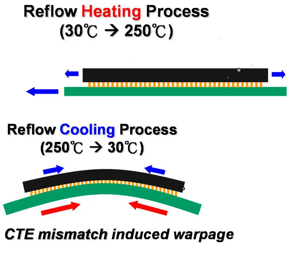
Automotive environments expose PCBs to significant temperature fluctuations, often ranging from subzero conditions to high heat near engines. These extremes cause uneven expansion and contraction of materials within the PCB. When layers with different coefficients of thermal expansion are bonded together, such as copper traces and dielectric substrates, thermal stress builds up. This mismatch is a primary driver of warpage in PCBs, as noted in guidelines like JEDEC J-STD-020E, which addresses moisture and reflow sensitivity during assembly.
During manufacturing, processes like soldering or lamination involve rapid heating and cooling cycles. If not controlled, these cycles exacerbate thermal stress, leading to permanent deformation. In operation, automotive PCBs in electric vehicles or near powertrain components face continuous heat dissipation challenges. Without proper design considerations, thermal stress accumulates, distorting the board over time and compromising interposer integrity in high-density interconnects.
Material Selection and Layer Imbalance
The choice of materials plays a critical role in the analysis of automotive warpage. PCBs are composite structures made of conductive and insulating layers. If the materials have mismatched properties or if the layer stackup is asymmetrical, internal stresses develop. For instance, an uneven distribution of copper across layers can create imbalance, causing the board to warp under thermal or mechanical load. Standards like IPC-A-600K provide criteria for acceptable board construction to minimize such risks.
In automotive PCBs, high layer counts and dense designs amplify these issues. Using materials with inconsistent glass transition temperatures or improper curing during lamination can further contribute to deformation. Engineers must prioritize balanced stackups and compatible materials to reduce stress points, ensuring the board remains flat under varying conditions encountered in vehicles.
Mechanical Stress and Assembly Processes
Mechanical stress during assembly or installation is another key factor in warpage. Automotive PCBs often undergo multiple handling steps, including component placement, soldering, and mounting into enclosures. Excessive pressure or improper support during these processes can induce bending. Additionally, reflow soldering, if not optimized, can cause uneven heating, leading to localized warpage as outlined in JEDEC J-STD-020E.
Vibrations and shocks in automotive applications add to mechanical stress over time. PCBs mounted in areas prone to constant movement may experience fatigue, worsening any pre-existing warpage. Ensuring proper fixturing and controlled assembly conditions is vital to prevent initial deformation that could compromise long-term reliability.
Impacts of Warpage on Automotive Electronics
Warpage in PCBs directly affects the performance and reliability of automotive systems. Misaligned components due to a warped board can lead to poor solder connections, increasing the risk of open circuits or shorts. This is particularly critical in high-density designs where interposer integrity is essential for maintaining signal integrity between layers or chips.
In safety-critical systems like braking or steering controls, even minor failures can have catastrophic consequences. Warpage also complicates assembly automation, as warped boards may not fit into pick-and-place machines or enclosures properly. Over time, continuous stress from warpage can cause microcracks in solder joints or traces, leading to intermittent failures. Addressing warpage is not just a manufacturing concern but a fundamental requirement for ensuring vehicle safety and compliance with standards like IPC-6012E.
Practical Solutions to Mitigate Warpage in Automotive PCBs
Design Optimization for Balance and Stability
Preventing warpage starts at the design stage. Engineers should aim for symmetrical layer stackups to balance stresses across the board. Distributing copper evenly on both sides of the PCB minimizes thermal and mechanical imbalances. Additionally, selecting materials with similar thermal expansion properties reduces stress during temperature changes. Guidelines in IPC-A-600K offer detailed recommendations for achieving balanced constructions.
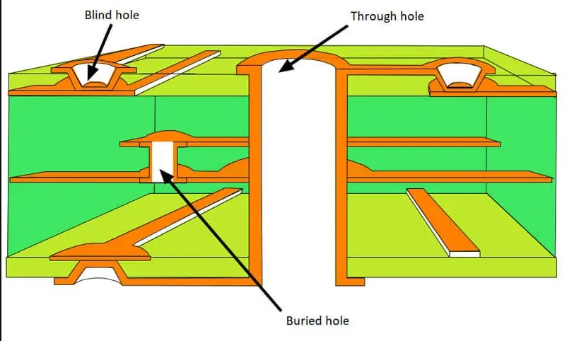
Incorporating stiffeners or reinforcing structures in high-stress areas can also enhance stability. For multilayer automotive PCBs, maintaining interposer integrity requires careful via placement and routing to avoid stress concentration points. Simulation tools aligned with industry standards can predict potential warpage during design, allowing for adjustments before production.
Material and Process Control
Choosing appropriate materials is crucial for minimizing warpage in PCBs. High-quality laminates with consistent properties and proper curing profiles should be selected. Controlling the lamination process to avoid overpressure or uneven heating prevents built-in stresses. Adhering to JEDEC J-STD-020E during reflow ensures that moisture sensitivity does not exacerbate warpage risks.
During assembly, maintaining uniform temperature profiles across the board is essential. Gradual heating and cooling cycles reduce thermal shock, while proper support fixtures prevent mechanical bending. Regular inspection using flatness measurement techniques, as recommended by IPC-6012E, helps detect early signs of warpage before boards proceed to final assembly.
Environmental Testing and Standards Compliance
Automotive PCBs must undergo rigorous environmental testing to validate their resistance to warpage under real-world conditions. Thermal cycling, humidity exposure, and vibration tests simulate the harsh environments vehicles encounter. Standards like ISO 9001:2015 provide frameworks for quality management to ensure consistent manufacturing practices that minimize defects.
Implementing strict quality control checks at each stage, from material selection to final assembly, ensures compliance with industry benchmarks. Flatness measurements and stress analysis, as per IPC-A-600K, should be routine to catch deviations early. By aligning with these standards, engineers can build confidence in the durability of automotive PCBs against warpage.
Related Reading: Minimizing Warpage in Multilayer PCB Manufacturing: Causes and Cures
Advanced Insights for Electrical Engineers
For engineers focused on high-performance automotive systems, understanding the interplay between design, materials, and processes is key to tackling warpage. In electric vehicles, where power electronics generate significant heat, integrating thermal management solutions like embedded heat sinks can mitigate thermal stress. This approach aligns with best practices for maintaining interposer integrity in dense interconnects.
Additionally, adopting advanced manufacturing techniques, such as controlled depth milling for balanced stackups, can further reduce warpage risks. Regular collaboration with material suppliers to stay updated on low-stress laminates ensures designs remain cutting edge. Engineers should also leverage failure analysis from field data to refine designs, ensuring continuous improvement in addressing the analysis of automotive warpage.
Conclusion
Warpage in PCBs poses a significant challenge in automotive applications, driven by thermal stress, material mismatches, and mechanical factors. This deformation threatens interposer integrity, component alignment, and overall system reliability. Through careful design optimization, material selection, and adherence to standards like IPC-6012E and JEDEC J-STD-020E, engineers can effectively mitigate these risks. The analysis of automotive warpage underscores the need for proactive measures, from balanced stackups to rigorous testing. By implementing the solutions outlined, electrical engineers can ensure that automotive PCBs meet the demanding requirements of modern vehicles, delivering safety and performance under extreme conditions.
FAQs
Q1: What are the primary causes of warpage in PCBs used in automotive systems?
A1: Warpage in PCBs often results from thermal stress due to temperature extremes in automotive environments. Material mismatches and uneven layer stackups contribute to internal stresses. Mechanical handling during assembly or vibrations in operation can also induce bending. Standards like IPC-6012E highlight the need for balanced designs to prevent such issues, ensuring reliability in critical vehicle systems.
Q2: How does warpage affect interposer integrity in multilayer automotive PCBs?
A2: Warpage disrupts interposer integrity by causing misalignment between layers or components in multilayer PCBs. This can lead to poor connections, signal loss, or mechanical failure in high-density designs. Stress from bending may also create microcracks over time. Following guidelines in JEDEC J-STD-020E during assembly helps minimize risks, maintaining robust interconnects in automotive applications.
Q3: What steps can engineers take during the analysis of automotive warpage?
A3: During the analysis of automotive warpage, engineers should evaluate thermal expansion mismatches and layer imbalances using simulation tools. Measuring flatness as per IPC-A-600K standards identifies early deformation. Testing under environmental conditions like thermal cycling reveals stress points. These steps allow for design adjustments and material selection to prevent warpage in vehicle electronics.
Q4: How can design practices reduce warpage in PCBs for automotive use?
A4: Designing symmetrical stackups and distributing copper evenly across layers reduces stress, preventing warpage in PCBs. Selecting materials with compatible thermal properties minimizes expansion mismatches. Incorporating stiffeners in high-stress areas adds stability. Adhering to IPC-6012E ensures flatness tolerances are met, enabling reliable performance in automotive systems under harsh conditions.
References
IPC-6012E — Qualification and Performance Specification for Rigid Printed Boards. IPC, 2020.
IPC-A-600K — Acceptability of Printed Boards. IPC, 2020.
JEDEC J-STD-020E — Moisture/Reflow Sensitivity Classification. JEDEC, 2014.
ISO 9001:2015 — Quality Management Systems. ISO, 2015.