Introduction
FR-4 printed circuit boards form the backbone of modern electronics, offering a reliable and cost-effective substrate for a wide range of applications. As the most common material for PCBs, FR-4's epoxy resin and fiberglass composition provide durability and thermal stability, making it ideal for various soldering processes. For electrical engineers, mastering soldering techniques on FR-4 boards is critical to ensure robust connections and prevent damage to components or the board itself. This guide explores essential soldering methods, including SMT soldering tips, through hole soldering techniques, reflow soldering for FR-4 PCBs, manual soldering, and lead free soldering practices. It also covers recommended PCB soldering equipment to achieve consistent, high-quality results. Whether you're assembling prototypes or overseeing mass production, understanding these best practices will enhance reliability and performance in your projects.
What Is FR-4 PCB Soldering and Why It Matters
FR-4 refers to a grade of flame-retardant, glass-reinforced epoxy laminate widely used in PCB manufacturing. Its thermal and mechanical properties make it suitable for soldering, a process that joins electronic components to the board by melting a filler metal, known as solder, to form a conductive bond. Soldering on FR-4 PCBs is foundational in electronics assembly, directly impacting the functionality and longevity of devices.
Proper soldering techniques are vital to avoid issues like thermal damage to the FR-4 material, poor joint integrity, or component failure. Incorrect methods can lead to delamination, pad lifting, or insufficient electrical connections, compromising the entire circuit. For electrical engineers, understanding how to adapt soldering approaches to FR-4's characteristics ensures compliance with industry standards and meets the demands of modern, high-density designs. With the rise of lead free soldering and complex surface mount technology, mastering these skills is more important than ever.
Technical Principles of Soldering on FR-4 PCBs
Soldering involves creating a metallurgical bond between the component leads or pads and the PCB's copper traces. The process relies on heat to melt solder, typically a tin-based alloy, which then solidifies to form a connection. FR-4 PCBs have a glass transition temperature, often around 130 to 140 degrees Celsius for standard grades, beyond which the material risks softening or degrading. This thermal limit shapes the choice of soldering techniques and temperature profiles.
Key principles include wetting, where molten solder spreads over the surfaces to form a bond, and intermetallic compound formation, which ensures long-term joint strength. Flux, a chemical agent, is used to remove oxides from surfaces, aiding wetting. Different soldering methods, such as reflow soldering for FR-4 PCBs or manual soldering, apply these principles in unique ways, each suited to specific component types or production scales. Controlling heat exposure is critical to prevent damage to FR-4's epoxy matrix or components.
Soldering Techniques for FR-4 PCBs
Surface Mount Technology Soldering Tips
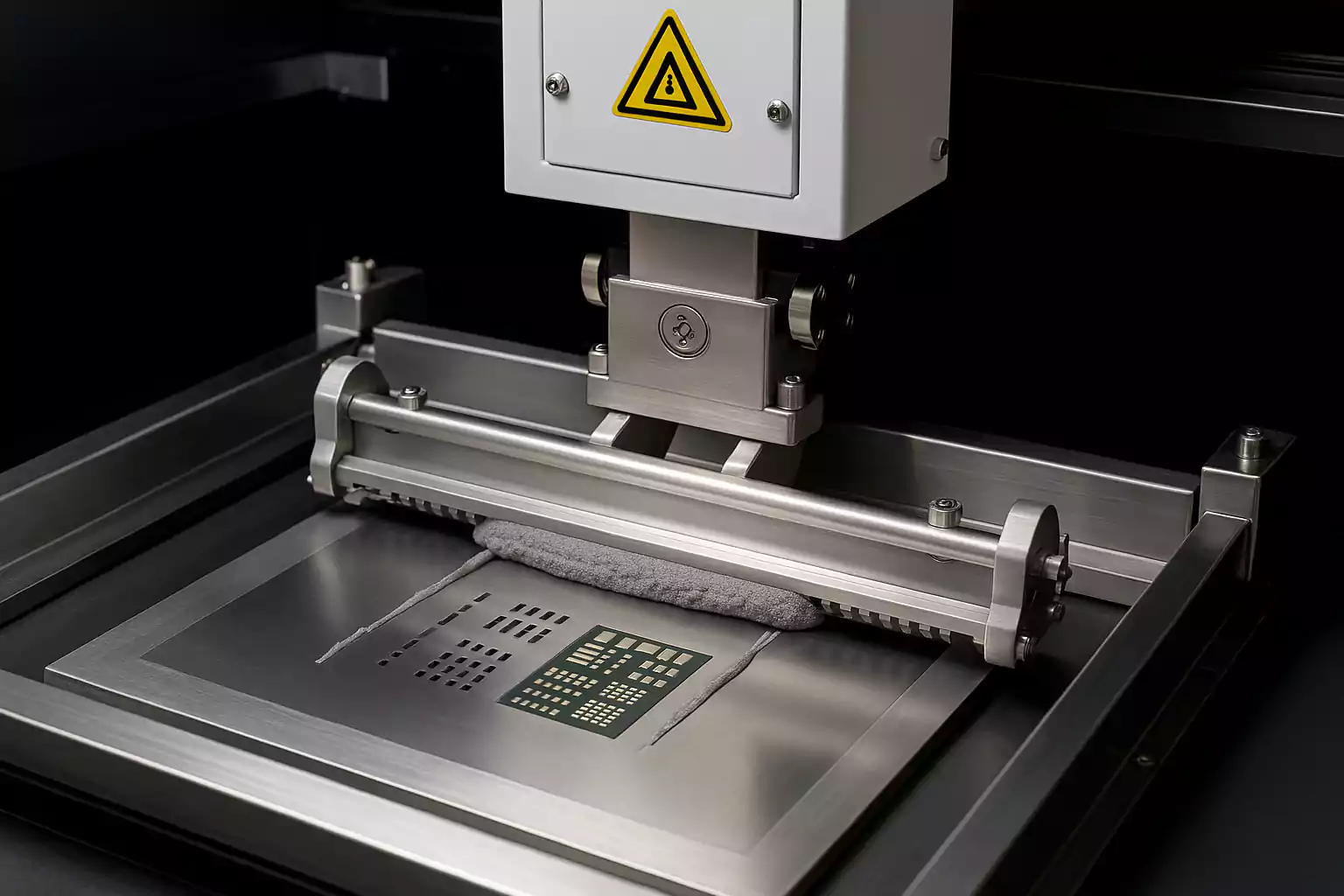
Surface mount technology, or SMT, involves attaching components directly to the PCB surface, a common approach for compact, high-density designs. SMT soldering tips focus on precision and thermal management to protect FR-4 boards. Start by applying solder paste, a mix of solder particles and flux, to the pads using a stencil. Place components accurately with tweezers or automated pick-and-place machines. Heat the board in a controlled manner, often via reflow soldering, to melt the paste and form joints.
Avoid excessive heat by adhering to recommended temperature profiles, as outlined in standards like JEDEC J-STD-020E. Monitor peak temperatures to stay within FR-4's thermal limits. Use a hot air rework station for repairs, ensuring localized heating to prevent board warpage. Clean residues post-soldering with appropriate solvents to prevent corrosion.
Through Hole Soldering Techniques
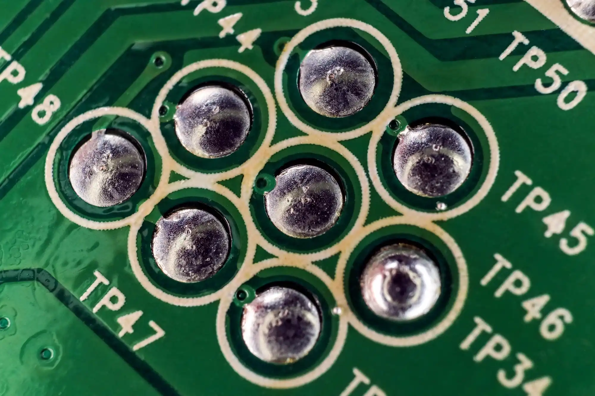
Through hole soldering techniques apply to components with leads inserted into drilled holes on the PCB, offering robust mechanical connections. Begin by inserting component leads into the holes, ensuring they are seated properly. Apply flux to the leads and pads to enhance wetting. Heat the pad and lead simultaneously with a soldering iron, then introduce solder to form a concave fillet around the lead.
Control iron temperature to avoid overheating the FR-4 material, typically keeping it below 300 degrees Celsius for short durations. Use a soldering iron with fine tip control for precision. After soldering, trim excess leads and inspect joints for consistency, following guidelines in IPC-A-600K for acceptability criteria. This method suits larger components or designs requiring extra durability.
Reflow Soldering for FR-4 PCBs
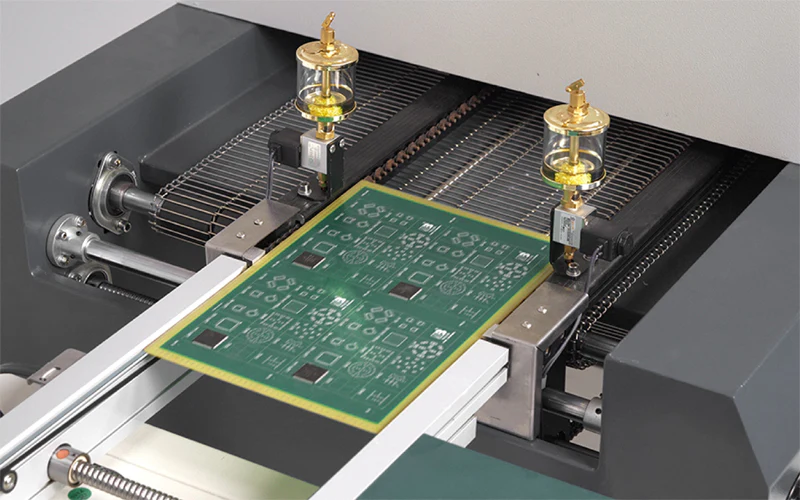
Reflow soldering for FR-4 PCBs is a widely used process in SMT PCB assembly, involving a controlled heating cycle to melt solder paste and secure components. The process occurs in a reflow oven with multiple temperature zones: preheat, soak, reflow, and cooling. During preheat, the board warms gradually to activate flux. The soak zone stabilizes temperatures, while the reflow zone melts solder at peak heat. Cooling solidifies the joints.
Adhering to a proper temperature profile, as specified in JEDEC J-STD-020E, prevents thermal shock to FR-4 boards. Limit peak temperatures and duration to avoid delamination or component stress. Nitrogen atmospheres in ovens can reduce oxidation, improving joint quality. Regularly calibrate ovens to maintain accuracy in thermal profiles.
Manual Soldering Best Practices
Manual soldering remains essential for prototyping, repairs, or small-scale production on the FR-4 PCB. Use a temperature-controlled soldering iron to match the solder alloy's melting point, avoiding excessive heat that could damage the board. Apply flux to clean surfaces before soldering, ensuring better adhesion. Touch the iron tip to both the pad and component lead, then add solder to form a smooth joint.
Work quickly to minimize heat exposure, especially with lead free soldering, which often requires higher temperatures. Inspect joints visually for defects like cold solder or bridging, referencing IPC-A-600K for quality standards. Use desoldering tools like braid or pumps for rework, protecting nearby components with heat-resistant tape.
Lead Free Soldering Considerations
Lead free soldering has become standard due to environmental regulations, using alloys like tin-silver-copper instead of traditional tin-lead mixtures. These alloys have higher melting points, often requiring adjustments in equipment and techniques for FR-4 PCBs. Increase soldering temperatures cautiously, ensuring they remain within the board's thermal limits to prevent damage.
Select compatible flux to handle the reduced wettability of lead free alloys. Monitor joint reliability, as these solders can be more prone to issues like tin whiskers over time. Follow IPC-6012E guidelines for performance specifications to ensure consistent results. Proper training in handling higher temperatures is essential for engineers to maintain quality.
PCB Soldering Equipment Essentials
Choosing the right PCB soldering equipment significantly impacts the quality of connections on FR-4 boards. Temperature-controlled soldering irons are fundamental for manual soldering, allowing precise heat adjustments. Reflow ovens with multiple zones are crucial for SMT processes, ensuring uniform heating across the board. Hot air rework stations aid in component removal or replacement without damaging surrounding areas.
Flux dispensers and solder paste applicators improve accuracy in applying materials. Desoldering tools, such as suction pumps or braid, are necessary for corrections. Magnifying tools or inspection microscopes help verify joint quality, aligning with IPC-A-600K standards. Invest in equipment with reliable calibration to maintain consistent performance during assembly.
Troubleshooting Common Soldering Issues on FR-4 PCBs
Soldering defects can compromise FR-4 PCB performance, requiring systematic troubleshooting. Cold solder joints, appearing dull or cracked, often result from insufficient heat or poor wetting. Reheat the joint with adequate flux to resolve this. Solder bridging, where excess solder connects adjacent pads, can be fixed by removing surplus material with desoldering braid.
Tombstoning in SMT occurs when components lift during reflow soldering for FR-4 PCBs, often due to uneven heating or pad design. Adjust reflow profiles and ensure balanced pad layouts to mitigate this. Delamination of FR-4 layers may happen from excessive heat; review temperature settings to stay within safe limits. Regular inspection against IPC-A-600K criteria helps identify and address issues early.
Conclusion
Soldering on FR-4 PCBs demands a deep understanding of material properties and process control to achieve reliable electronic assemblies. From SMT soldering tips to through hole soldering techniques, each method requires tailored approaches to prevent thermal damage and ensure strong connections. Reflow soldering for FR-4 PCBs, manual soldering practices, and lead free soldering considerations all play critical roles in modern electronics manufacturing. Equipped with the right PCB soldering equipment and adherence to industry standards, electrical engineers can consistently produce high-quality results. By mastering these best practices, you ensure the durability and performance of your PCB designs in any application.
FAQs
Q1: What are the key SMT soldering tips for FR-4 PCBs?
A1: For SMT soldering on FR-4 PCBs, precision is crucial. Use a stencil to apply solder paste evenly on pads, place components accurately, and follow a controlled reflow profile to avoid thermal stress. Limit heat exposure to protect the board, and clean residues afterward to prevent corrosion. Following standards like JEDEC J-STD-020E ensures reliable joints.
Q2: How does reflow soldering for FR-4 PCBs differ from other methods?
A2: Reflow soldering for FR-4 PCBs involves heating the entire board in an oven with defined temperature zones to melt solder paste for SMT components. Unlike manual soldering, it automates the process for high-volume production. It requires strict temperature control to prevent FR-4 damage, guided by standards like JEDEC J-STD-020E.
Q3: What challenges arise with lead free soldering on FR-4 boards?
A3: Lead free soldering on FR-4 PCBs often requires higher temperatures due to the alloys' elevated melting points, risking thermal damage to the board. Wettability is reduced, necessitating compatible flux. Joint reliability must be monitored for issues like tin whiskers. Adhering to IPC-6012E helps maintain quality during assembly.
Q4: What PCB soldering equipment is essential for through hole soldering techniques?
A4: For through hole soldering techniques, a temperature-controlled soldering iron is vital to prevent overheating FR-4 material. Flux applicators ensure clean surfaces, while desoldering tools like braid or pumps aid rework. Inspection tools, aligned with IPC-A-600K standards, help verify joint quality for robust mechanical connections.
References
IPC-6012E — Qualification and Performance Specification for Rigid Printed Boards. IPC, 2020.
IPC-A-600K — Acceptability of Printed Boards. IPC, 2020.
JEDEC J-STD-020E — Moisture/Reflow Sensitivity Classification. JEDEC, 2014.


