Introduction
Printed Circuit Board (PCB) manufacturing relies on precise data to ensure every component fits and functions as intended. Among the critical elements in this process are PCB drill files, which define the locations and sizes of holes for vias, mounting points, and other features. These files, often in formats like Excellon and Gerber, serve as instructions for CNC drilling machines. Understanding their structure, purpose, and integration with PCB manufacturing data is essential for electrical engineers aiming to achieve flawless production. This guide explores the intricacies of drill files, including formats like Excellon, the role of Gerber files, and best practices for creating accurate drill charts and tables. By mastering these elements, engineers can minimize errors and streamline the transition from design to fabrication.
What Are PCB Drill Files and Why Do They Matter
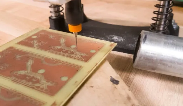
PCB drill files are digital documents that specify the coordinates, sizes, and types of holes to be drilled into a circuit board during manufacturing. These holes are categorized as Plated Through Holes (PTH) for electrical connections and Non-Plated Through Holes (NPTH) for mechanical purposes like mounting. Drill files are crucial because they directly impact the board's functionality and structural integrity. Without accurate data, misaligned or incorrectly sized holes can lead to assembly failures or electrical shorts.
In the context of PCB manufacturing data, drill files work alongside other outputs like Gerber files to provide a complete picture for fabricators. They ensure that CNC drilling equipment operates with precision, aligning holes with copper traces and pads. For electrical engineers, understanding drill files is vital to bridge the gap between design intent and production reality, ensuring reliability in every board.
Related Reading: Why is PCB Drilling Essential To Making Your Planned PCB Layout Work?
Technical Principles of PCB Drill Files
Understanding Excellon Format
The Excellon format is a widely accepted standard for PCB drill files, originally developed for CNC drilling and routing equipment. It is a text-based format that includes commands for drill coordinates, tool sizes, and machine operations. Each line in an Excellon file typically specifies an X and Y coordinate for a hole, along with the tool number corresponding to the drill bit size. This format also supports metadata like feed rate and spindle speed, which are critical for optimizing drilling performance.
Excellon files are essential for their simplicity and compatibility with most CNC drilling systems. They allow engineers to define both PTH and NPTH with precision, ensuring that the drilling process aligns with the design's electrical and mechanical requirements. Standards such as IPC-NC-349 provide guidelines for formatting numerical control data, which includes Excellon, to maintain consistency across tools and manufacturers.
Role of Gerber Files in Drilling Context
While Gerber files primarily define the copper layers, solder masks, and silkscreen of a PCB, they are often used in conjunction with drill files to provide a complete manufacturing dataset. Gerber files, based on the RS-274X standard, can include aperture lists and layer information that indirectly relate to drilling by defining pad sizes and locations. However, they do not replace dedicated drill files like Excellon, as they lack specific CNC drilling instructions.
For electrical engineers, integrating Gerber files with drill data ensures that the drilled holes align perfectly with copper features. Misregistration between these datasets can result in vias that fail to connect or pads that are partially drilled, compromising the board's functionality. Adhering to standards like IPC-2581, which supports comprehensive data exchange, helps maintain accuracy across different file types.
CNC Drilling and Drill Data Specifications
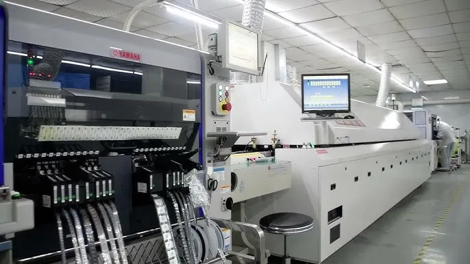
CNC drilling is the process of using computer-controlled machines to create holes in PCBs based on drill file instructions. These machines rely on precise data from files like Excellon to select the correct drill bit, position the board, and execute the drilling with minimal deviation. Key parameters in drill files include hole diameter, tolerance, and whether the hole is plated or non-plated.
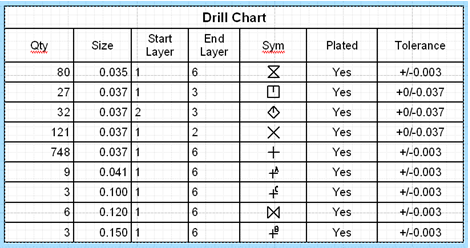
Drill charts and drill tables are often included as part of the PCB manufacturing data package. A drill chart visually represents hole sizes and locations, while a drill table lists each hole's specifications, including diameter and quantity. These tools help fabricators verify data before drilling and assist engineers in cross-checking design outputs against manufacturing capabilities.
Related Reading: What Type Of Drill Bits Should I Have When Drilling a PCB?
Practical Solutions for Creating and Managing Drill Files
Generating Accurate Drill Files
Creating accurate PCB drill files starts with proper design software setup. Most electronic design automation tools allow engineers to export drill data in Excellon format, ensuring compatibility with CNC drilling equipment. During export, it is crucial to define all hole types, distinguishing between PTH and NPTH, as this affects plating processes. Engineers should also specify drill sizes and tolerances according to fabrication limits, often guided by standards like IPC-6012E for rigid board performance.
Before finalizing drill files, a thorough review of coordinates and tool assignments is necessary. Errors in X and Y positions can lead to misaligned holes, while incorrect tool numbers may result in wrong hole sizes. Using design rule checks aligned with IPC-A-600K for board acceptability can help identify issues early in the process.
Best Practices for Drill Charts and Tables
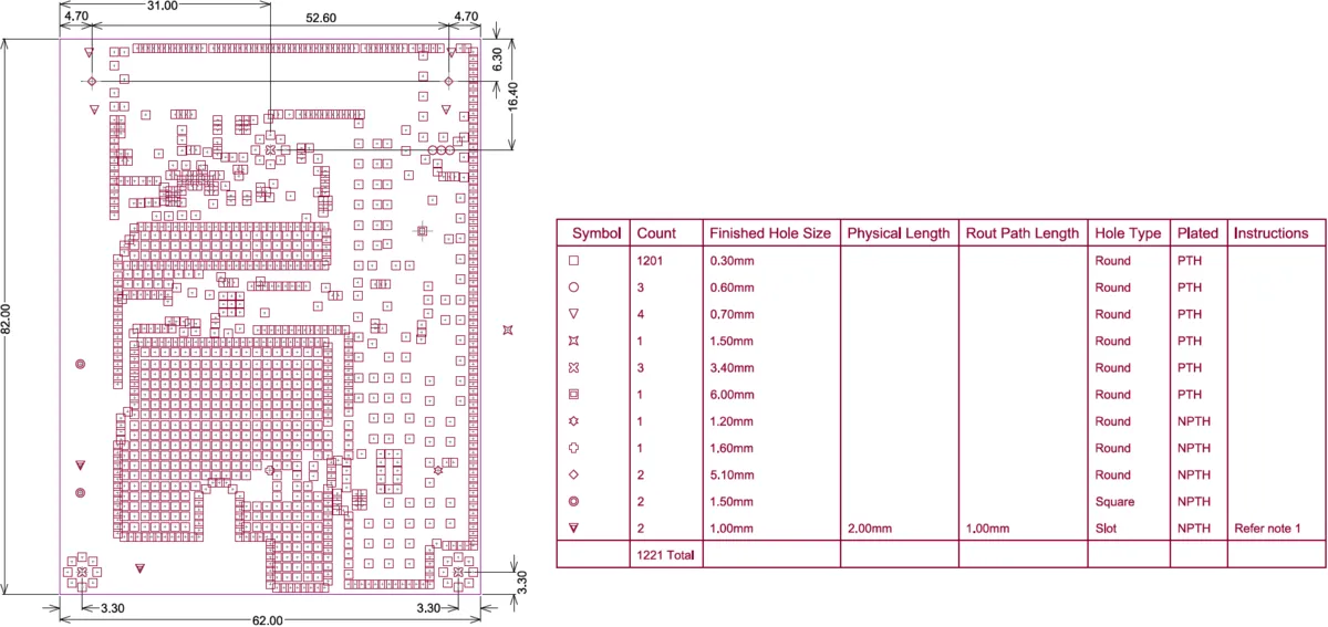
Including a drill chart and drill table with PCB manufacturing data enhances clarity for fabricators. A well-structured drill table should list each hole size, its count, whether it is PTH or NPTH, and associated tolerances. This table acts as a reference to confirm that the drill file matches the design intent. A drill chart, on the other hand, provides a visual map of hole locations, often overlaid on the board outline for quick validation.
Engineers should ensure that these documents are consistent with the digital drill files. Discrepancies can cause delays or errors during manufacturing. Cross-referencing with standards like IPC-2581 for data exchange formats ensures that all stakeholders interpret the information uniformly.
Avoiding Common Errors in Drill Files
Common issues with PCB drill files include incorrect hole classifications, missing tools, and format incompatibilities. Mislabeling a PTH as NPTH can lead to unplated vias, disrupting electrical connectivity. Missing tool definitions in Excellon files may cause the CNC drilling machine to skip holes or use incorrect bits. Format issues arise when older or non-standard file structures are used, leading to misinterpretation by modern equipment.
To mitigate these risks, engineers should validate files using software previews and adhere to recognized formats as outlined in IPC-NC-349. Collaboration with fabricators to confirm file compatibility before production is also advisable. Regular updates to design tools ensure support for current standards, reducing the likelihood of errors.
Integration of Drill Files with Overall PCB Manufacturing Data
PCB drill files do not exist in isolation. They are part of a broader set of PCB manufacturing data that includes Gerber files for layer definitions, netlists for connectivity, and bills of materials for components. Seamless integration of these elements ensures that drilling aligns with copper traces, solder masks, and assembly requirements. For instance, a drilled via must match the pad size defined in the Gerber file to ensure proper plating and soldering.
Standards like IPC-2581 provide a framework for combining different data types into a unified package, minimizing the risk of miscommunication between design and manufacturing stages. Engineers should prioritize generating all files from a single design source to maintain consistency. Validation tools that check registration between drill and Gerber data can further enhance accuracy.
Troubleshooting Drill File Issues
When issues arise during CNC drilling, such as misaligned holes or incorrect sizes, the root cause often lies in the drill file or its integration with other data. Engineers should first verify the Excellon file for syntax errors or missing commands. Comparing the drill table against the actual file output can reveal discrepancies in hole counts or specifications. If registration with Gerber files is off, checking the coordinate system used during export is necessary.
Another common problem is tool mismatch during CNC drilling. If the fabricator's equipment does not support a specified drill bit, substitutions may occur without notice. Providing a clear drill chart and communicating tolerances based on IPC-6012E can prevent such issues. Keeping an open dialogue with manufacturing teams ensures quick resolution of discrepancies.
Conclusion
Mastering PCB drill files is a fundamental skill for electrical engineers involved in design and manufacturing. Formats like Excellon provide the precision needed for CNC drilling, while integration with Gerber files ensures alignment with other board features. By adhering to industry standards and employing best practices for drill charts and tables, engineers can avoid common pitfalls and achieve reliable results. Understanding the distinction between PTH and NPTH, along with meticulous validation of PCB manufacturing data, further enhances production quality. This guide serves as a foundation for navigating the complexities of drill files, empowering professionals to deliver robust and functional circuit boards.
FAQs
Q1: What is the difference between PTH and NPTH in PCB drill files?
A1: Plated Through Holes (PTH) are holes with conductive plating to connect layers electrically, vital for vias and component leads. Non-Plated Through Holes (NPTH) lack plating and serve mechanical purposes like mounting. Correctly specifying these in PCB drill files ensures proper functionality and structural integrity during manufacturing, as misclassification can disrupt connectivity or assembly.
Q2: How does the Excellon format support CNC drilling processes?
A2: The Excellon format provides detailed instructions for CNC drilling, including hole coordinates and tool sizes. It supports machine-specific data like feed rates, ensuring precise hole creation. Widely compatible with equipment, it enables accurate execution of drilling tasks, making it a cornerstone for engineers preparing PCB drill files for fabrication.
Q3: Why are drill charts important in PCB manufacturing data?
A3: Drill charts visually map hole locations and sizes, aiding fabricators in verifying PCB manufacturing data before drilling. They complement digital files like Excellon by offering a quick reference, reducing errors. For engineers, charts ensure design intent matches production, enhancing communication and minimizing costly mistakes during the process.
Q4: How do Gerber files relate to PCB drill files?
A4: Gerber files define copper layers and pad locations, complementing PCB drill files that specify hole positions. Proper alignment between them ensures drilled holes match electrical features. Using standards like IPC-2581, engineers integrate these datasets to prevent registration errors, maintaining board functionality across manufacturing stages.
References
IPC-6012E — Qualification and Performance Specification for Rigid Printed Boards. IPC, 2020.
IPC-A-600K — Acceptability of Printed Boards. IPC, 2020.
IPC-2581 — Generic Requirements for Printed Board Assembly Products Manufacturing Description Data and Transfer Methodology. IPC, 2021.
IPC-NC-349 — Computer Numerical Control Formatting for Drillers and Routers. IPC, 1985.