Introduction
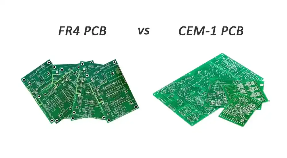
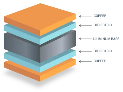
Metal core printed circuit boards (MCPCBs) represent a specialized class of PCBs designed to handle high thermal loads in demanding applications such as power electronics, LED lighting, and automotive systems. Unlike standard FR4 boards, MCPCBs feature a solid metal core, typically aluminum or copper, bonded to a thin thermally conductive dielectric layer and topped with copper circuitry. This construction provides a low-impedance path for heat dissipation directly from components to the core, which acts as a built-in heat spreader. As power densities increase in modern electronics, effective thermal management becomes essential to prevent hotspots, ensure component reliability, and extend operational life. Advanced techniques like thermal vias in MCPCB, MCPCB heat sinks, and thermal interface materials play pivotal roles in optimizing heat transfer. This article delves into these methods, offering factory-driven insights aligned with industry practices for electric engineers designing high-performance systems.
Understanding MCPCBs and the Need for Advanced Thermal Management
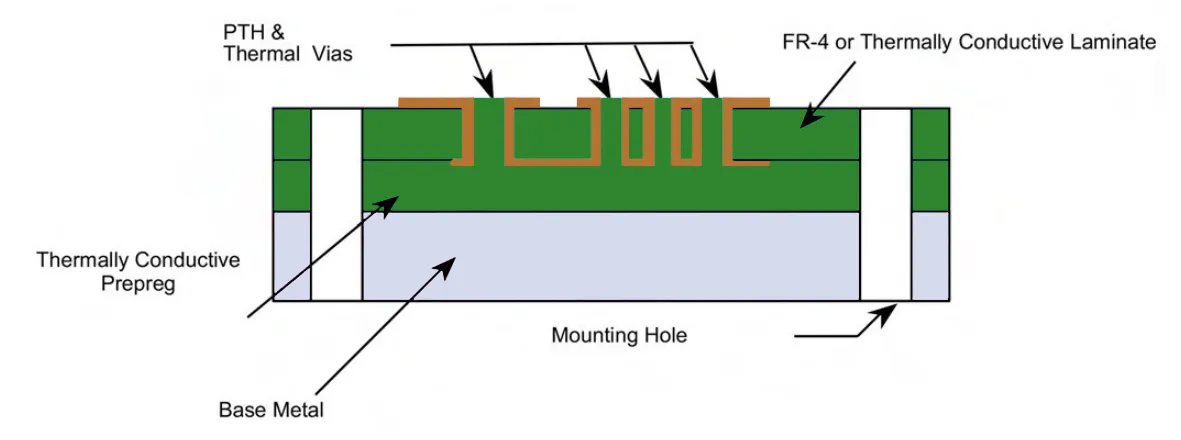
MCPCBs consist of a base metal plate that serves as the primary heat sink, insulated by a dielectric layer with enhanced thermal conductivity compared to standard prepregs. The metal core spreads heat laterally across a large area, facilitating dissipation through conduction to external cooling elements or ambient air. This structure is particularly valuable in environments where convection and radiation alone cannot suffice, such as densely packed power modules. Poor thermal management leads to elevated junction temperatures, accelerated material degradation, and potential failure modes like delamination or solder joint fatigue. Industry relevance stems from the growing adoption of MCPCBs in sectors requiring robust heat handling without bulky external cooling. Engineers must prioritize thermal pathways during design to align with performance specifications and manufacturing capabilities.
The thermal performance of MCPCBs hinges on minimizing resistance along the heat flow path from the heat-generating component to the ultimate dissipator. Factory processes emphasize precise control of dielectric thickness and bonding to maintain low thermal impedance while ensuring electrical isolation. Compliance with standards like IPC-6012 for qualification helps verify that boards meet rigid performance criteria under thermal stress. Why it matters: In high-reliability applications, suboptimal heat dissipation can compromise system integrity, leading to rework or field failures. By integrating advanced techniques, designers achieve balanced electrical and thermal functionality in compact footprints.
Core Principles of Heat Dissipation in MCPCBs
Heat dissipation in MCPCBs primarily occurs through conduction, governed by Fourier's law, where heat flux is proportional to the temperature gradient and material conductivity. The metal core's high thermal conductivity, combined with the thin dielectric, creates a direct thermal path MCPCB that bypasses the limitations of multilayer FR4 stacks. Thermal resistance accumulates along this path, influenced by layer thicknesses, material properties, and interface quality. Engineers model these paths using finite element analysis to predict hotspots and optimize layouts. Radiation and convection contribute secondarily, enhanced by surface finishes and airflow. Understanding these mechanisms enables targeted improvements in MCPCB cooling solutions.
Key to effective dissipation is the creation of low-resistance conduits that channel heat vertically and horizontally. Thermal vias in MCPCB serve as vertical conduits, plated-through holes that transfer heat from top-side components to the core or bottom layers. Copper planes act as spreaders, distributing heat evenly to prevent localized overheating. Factory insights reveal that symmetrical stackups reduce warpage during thermal cycling, preserving interface integrity. Direct attachment strategies further shorten paths, minimizing impedance drops.
Thermal Vias in MCPCB: Enhancing Vertical Heat Transfer
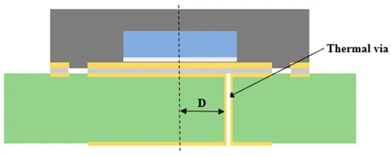
Thermal vias in MCPCB are arrays of small plated holes positioned under heat sources, such as power ICs or LEDs, to conduct heat perpendicularly through the board. These vias leverage the high conductivity of copper plating to bridge layers, often connected to ground or power planes for additional spreading. In MCPCBs, vias efficiently route heat to the metal core, significantly lowering thermal resistance compared to lateral conduction alone. Best practices include using via-in-pad configurations for direct component attachment, with diameters optimized for plating uniformity and solder wicking prevention. Filled vias, using conductive epoxy or copper plugs, further boost performance by eliminating air gaps and providing capped surfaces for reliable soldering.
Placement strategy involves grids or patterns directly beneath thermal pads, ensuring even distribution without interfering with signal integrity. Factory-driven advice stresses tenting non-critical vias with solder mask while leaving thermal ones open or filled to maximize conductivity. Aspect ratios should stay below 10:1 to ensure void-free plating during fabrication. Combining vias with oversized copper pads amplifies spreading, creating a robust MCPCB cooling solution. Simulations validate via count and spacing, aligning designs with IPC-2152 guidelines for thermal reliability.
Integrating MCPCB Heat Sinks for Superior Dissipation
An MCPCB heat sink attaches directly to the exposed metal core or bottom copper, leveraging the board's inherent spreading for efficient external cooling. Aluminum fins or pin configurations increase surface area for convection, while the core provides a stable mounting base. This combination excels in passive cooling scenarios, where forced air enhances performance without active components. Selection considers fin density, base material compatibility, and mounting pressure to avoid core deformation. Factory processes often include machined slots or V-scoring for precise heat sink alignment during assembly.
Thermal interface materials fill microscopic gaps between the MCPCB and heat sink, reducing contact resistance and ensuring uniform heat transfer. Grease, pads, or phase-change materials serve this role, selected based on operating temperatures and rework needs. Direct thermal path MCPCB designs position heat sources over large core areas, maximizing sink efficacy. Engineers benefit from pre-testing assemblies to confirm low junction-to-sink resistance.
Role of Thermal Interface Materials in MCPCB Designs
Thermal interface materials (TIMs) are critical in MCPCB assemblies, bridging dissimilar surfaces to minimize air-induced thermal barriers. In direct thermal path MCPCB configurations, TIMs coat component bases or core interfaces, enabling unimpeded conduction to sinks. High-conductivity variants, filled with ceramics like alumina or boron nitride, outperform standard adhesives while maintaining electrical isolation. Application techniques include screen printing for uniformity, avoiding excess that could lead to pump-out under thermal cycling. Factory validation involves shear strength and thermal cycling tests per ASTM standards.
Layered TIM strategies, such as pads over grease, accommodate tolerances in high-volume production. When paired with thermal vias in MCPCB, TIMs complete the dissipation chain from chip to ambient. Optimal thickness balances impedance with compliance, often guided by manufacturer datasheets.
Direct Thermal Path MCPCB and Hybrid Cooling Solutions
Direct thermal path MCPCB minimizes layers between heat sources and the core, using pedestal builds or cavity designs for near-direct attachment. This approach reduces path length, lowering overall resistance and enabling higher power densities. Oversized vias or filled holes insulate while conducting, common in LED arrays. Hybrid MCPCB cooling solutions combine passive elements like sinks with vias and selective active cooling, such as embedded heat pipes for extreme cases.
Best practices emphasize early fabricator involvement for stackup feasibility and panel utilization. JEDEC guidelines aid in characterizing thermal performance under standardized conditions. Comprehensive designs integrate all techniques for synergistic effects.
Design and Manufacturing Best Practices
Successful MCPCB thermal management requires holistic design, starting with component placement to centralize heat sources and facilitate airflow. Thicker copper pours and multi-oz weights enhance in-plane spreading, balanced against cost and etch factors. Fabrication tolerances for dielectric thickness directly impact conductivity, necessitating tight process controls. Post-fabrication, HiPot and thermal impedance testing confirm integrity.
Adhering to IPC-2152 for trace heating ensures electrical paths do not compound thermal loads. Multilayer MCPCBs bond additional circuits with conductive prepregs, expanding capabilities. Troubleshooting focuses on warpage mitigation through CTE-matched materials.
Conclusion
Advanced thermal management elevates MCPCBs from standard boards to high-performance platforms, addressing heat challenges in power-intensive applications. Techniques like thermal vias in MCPCB, MCPCB heat sinks, direct thermal path MCPCB, thermal interface materials, and integrated cooling solutions form a versatile toolkit. Factory-aligned practices, informed by standards, deliver reliable outcomes. Engineers implementing these methods achieve optimal dissipation, longevity, and efficiency.
FAQs
Q1: What are thermal vias in MCPCB and how do they improve heat dissipation?
A1: Thermal vias in MCPCB are plated through-holes under heat sources that conduct heat vertically to the metal core or planes. Arrays enhance spreading, reducing hotspots in high-power designs. Filled variants boost conductivity, aligning with manufacturing for reliable paths. This creates effective MCPCB cooling solutions without excessive board thickness.
Q2: How do MCPCB heat sinks contribute to overall thermal performance?
A2: MCPCB heat sinks attach to the core for direct conduction, expanding dissipation via fins for convection. Paired with TIMs, they minimize resistance from board to ambient. Factory mounting ensures stability, ideal for passive cooling in compact systems. This technique supports higher power handling reliably.
Q3: Why are thermal interface materials essential for direct thermal path MCPCB?
A3: Thermal interface materials fill gaps in direct thermal path MCPCB, ensuring low-resistance contact between components and core or sinks. They prevent air voids, maintaining conductivity under cycling. Selection focuses on viscosity and filler content for assembly ease. Essential for maximizing MCPCB heat sink efficacy.
Q4: What best practices optimize MCPCB cooling solutions?
A4: Optimize MCPCB cooling solutions by simulating paths, placing vias under sources, and using thick copper spreads. Comply with IPC-2152 for trace thermal loads and test per JEDEC for characterization. Collaborate with fabricators for stackup and filling. Integrates vias, sinks, and TIMs holistically.
References
IPC-2152 — Standard for Determining Current Carrying Capacity in Printed Board Traces. IPC, 2009
IPC-6012E — Qualification and Performance Specification for Rigid Printed Boards. IPC, 2017
JEDEC JESD51-10 — Guidelines for Controlling Stress in the Microelectronic Industry. JEDEC, 2010
ASTM E-1461 — Standard Test Method for Thermal Diffusivity by the Flash Method. ASTM, 2013