Introduction
Printed Circuit Board (PCB) mass production is a complex process that demands precision and adherence to strict standards to ensure functionality and reliability. Even minor errors during design, manufacturing, or assembly can lead to significant defects, costly rework, and delayed timelines. For electrical engineers, understanding common PCB manufacturing mistakes and mastering PCB defect troubleshooting are essential skills to maintain product quality.
This article explores frequent PCB assembly problems, offers practical PCB rework techniques, and provides actionable strategies for preventing PCB failures. By addressing these challenges with industry best practices and standardized approaches, engineers can minimize risks and optimize production outcomes. Join us as we break down these critical issues and solutions to enhance your manufacturing process.
Why PCB Mass Production Challenges Matter
Mass production of PCBs involves scaling up from prototype to thousands or millions of units, amplifying the impact of any error. A single oversight in design or process can result in widespread failures, affecting product reliability and brand reputation. For electrical engineers, the stakes are high as PCBs form the backbone of electronic devices across industries like automotive, medical, and consumer electronics.
Preventing PCB failures during mass production saves time, reduces costs, and ensures compliance with stringent quality requirements. Addressing PCB assembly problems early also avoids bottlenecks in supply chains. By focusing on common PCB manufacturing mistakes, teams can implement robust systems for PCB defect troubleshooting and improve overall yield in high volume scenarios.
Common Mistakes in PCB Mass Production
Design Related Errors
Many issues in mass production originate from the design phase. Incomplete or unclear design files often lead to misinterpretation during manufacturing. Missing layer stack up information or undefined board outlines can cause fabrication errors. Additionally, inadequate spacing between traces or components may violate clearance rules, risking short circuits or signal interference. Another frequent mistake is ignoring thermal management, leading to overheating in densely populated boards. These design flaws often become evident only during assembly or testing, making corrections expensive and time consuming.
Manufacturing Process Flaws
During fabrication, inconsistencies in material selection or process control can introduce defects. Using substandard laminates or improper copper plating may result in delamination or weak traces. Poor control over etching processes can lead to over or under etching, affecting trace integrity. Warpage is another issue, often caused by uneven heating or cooling during lamination, which impacts component placement accuracy. These manufacturing mistakes contribute to PCB assembly problems and require rigorous quality checks to identify and resolve.
Assembly Stage Issues
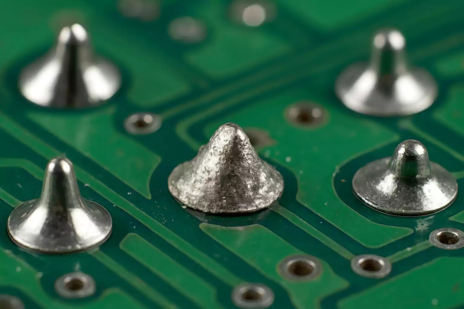
PCB assembly problems frequently arise from soldering defects or component misalignment. Cold solder joints, caused by insufficient heat during reflow, can create unreliable connections. Tombstoning, where components lift on one side, often results from uneven pad sizes or thermal profiles. Incorrect component placement due to outdated pick and place data also disrupts functionality. These errors necessitate effective PCB rework techniques to salvage boards and prevent scrap, especially in mass production environments.
Testing and Inspection Oversights
Skipping or inadequately performing inspections can allow defects to go unnoticed until the final product stage. Insufficient use of Automated Optical Inspection (AOI) or In Circuit Testing (ICT) may miss issues like open circuits or misplaced components. Failing to test for environmental stresses, such as thermal cycling, can overlook potential long term failures. These oversights in PCB defect troubleshooting can lead to costly recalls or field failures, emphasizing the need for thorough quality control.
Causes of PCB Failures in Mass Production
Understanding the root causes of failures is crucial for preventing PCB failures. Design errors often stem from non compliance with industry guidelines, leading to manufacturability issues. In manufacturing, variations in process parameters like temperature or pressure during lamination can weaken board structures. Assembly issues frequently arise from improper reflow profiles or inadequate stencil design, causing uneven solder paste application. Environmental factors, such as humidity or contamination, can also degrade board performance over time. Identifying these causes through systematic analysis helps engineers develop targeted solutions for consistent production quality.
Practical Solutions and Best Practices
Design Optimization
To avoid common PCB manufacturing mistakes, start with design validation against recognized standards like IPC 2221 for generic PCB design requirements. Ensure clear documentation of board outlines, layer stack ups, and drill files. Incorporate adequate spacing for traces and vias to prevent electrical interference. Use simulation tools to predict thermal behavior and adjust layouts for heat dissipation. These steps minimize design related errors before production begins, reducing the need for costly revisions.
Manufacturing Controls
Adhering to standards such as IPC 6012E for rigid board performance ensures material and process consistency. Implement strict controls over lamination temperatures and etching times to prevent warpage or trace damage. Regular calibration of equipment and monitoring of material batches can catch deviations early. These measures address manufacturing flaws and support reliable outcomes during mass production runs.
Assembly Improvements
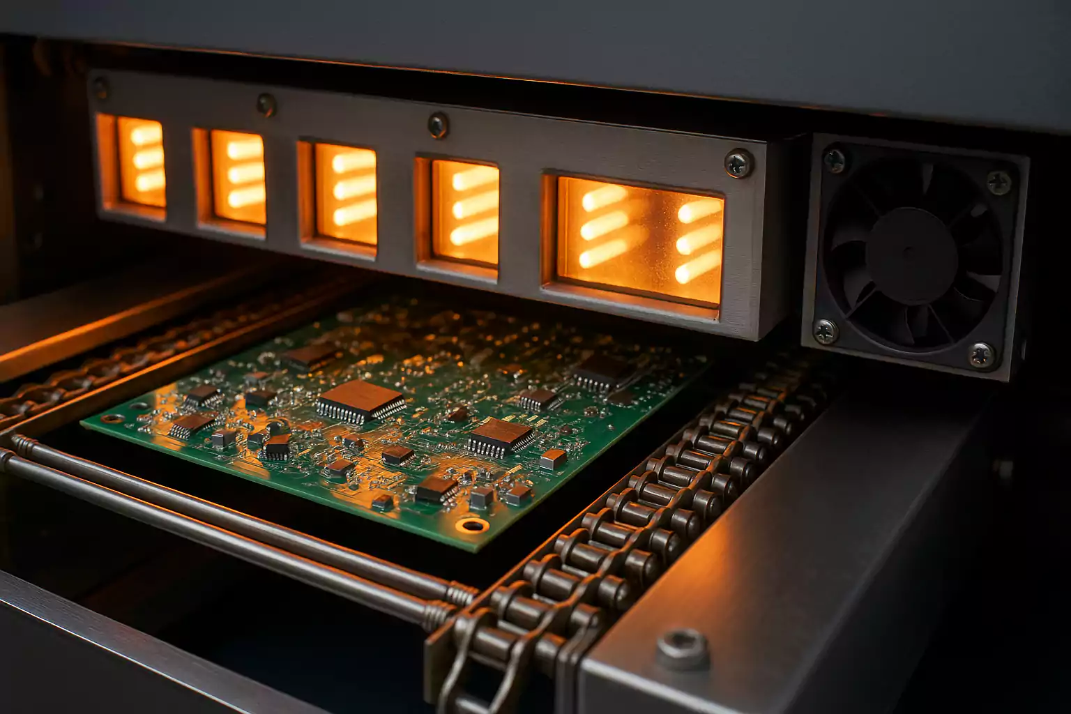
For PCB assembly problems, optimize reflow soldering profiles to match component specifications, preventing issues like cold joints or tombstoning. Use precise stencil designs to ensure uniform solder paste application. Update pick and place data regularly to avoid component misalignment. Following guidelines like IPC J STD 001 for soldered electrical assemblies helps maintain connection quality. These practices reduce defects and improve assembly yield.
Enhanced Inspection and Testing
Robust PCB defect troubleshooting relies on comprehensive inspection protocols. Employ AOI for visual defect detection and ICT for functional verification. Conduct environmental stress tests, such as thermal cycling, to simulate real world conditions. Adhering to IPC A 600K for board acceptability criteria ensures consistent quality evaluation. These testing methods identify issues early, allowing for timely corrections before products reach the market.
Rework Strategies
Effective PCB rework techniques are vital for salvaging defective boards. Use controlled heating tools for desoldering and replacing components without damaging nearby areas. Clean reworked areas thoroughly to remove flux residue, preventing corrosion. Document rework processes to track recurring issues and inform future design improvements. Following IPC 7711/7721 guidelines for rework and repair ensures reliable outcomes without compromising board integrity.
Troubleshooting Insights for Mass Production
In mass production, troubleshooting must be systematic to handle large volumes efficiently. Start by categorizing defects based on type, such as soldering issues or trace breaks, to identify patterns. Use failure analysis techniques, including cross sectional microscopy, to examine internal defects like delamination. Maintain detailed logs of production parameters and defect rates to correlate issues with specific process steps. Implement corrective actions promptly, adjusting design rules or assembly settings as needed. This structured approach to PCB defect troubleshooting minimizes downtime and prevents recurring failures across batches.
Conclusion
Navigating the complexities of PCB mass production requires a proactive stance against common PCB manufacturing mistakes. By understanding the root causes of defects, from design flaws to assembly errors, electrical engineers can implement robust solutions to prevent PCB failures. Adopting best practices in design validation, process control, and inspection ensures consistent quality at scale. Practical PCB rework techniques further mitigate losses by salvaging defective units. With adherence to industry standards and systematic PCB defect troubleshooting, production teams can achieve higher yields and reliable products, meeting the rigorous demands of modern electronics applications.
FAQs
Q1: What are the most common PCB manufacturing mistakes to watch for in mass production?
A1: In mass production, frequent mistakes include design errors like inadequate spacing, manufacturing issues such as warpage from uneven heating, and assembly flaws like cold solder joints. Following standards like IPC 6012E for board performance helps catch these early. Thorough documentation and process control are essential to avoid costly defects across large batches.
Q2: How can PCB defect troubleshooting improve production yield?
A2: PCB defect troubleshooting identifies root causes like soldering issues or trace damage through methods like AOI and ICT. By analyzing defect patterns and adjusting processes, engineers can reduce failure rates. This systematic approach, aligned with IPC A 600K guidelines, enhances yield by addressing problems before they escalate in mass production.
Q3: What PCB rework techniques are effective for assembly problems?
A3: Effective PCB rework techniques include using controlled heat for desoldering defective components and cleaning flux residue to prevent corrosion. Tools like hot air stations help avoid damage to nearby areas. Adhering to IPC 7711/7721 standards ensures reliable repairs, salvaging boards and minimizing scrap during assembly corrections.
Q4: How can engineers focus on preventing PCB failures during scaling?
A4: Preventing PCB failures involves validating designs per IPC 2221, optimizing reflow profiles, and conducting stress tests. Consistent material selection and calibrated equipment reduce manufacturing variability. Implementing strict quality checks and maintaining detailed logs during scaling helps catch issues early, ensuring reliability across high volume production runs.
References
IPC-6012E - Qualification and Performance Specification for Rigid Printed Boards. IPC, 2020.
IPC-A-600K - Acceptability of Printed Boards. IPC, 2020.
IPC-2221 - Generic Standard on Printed Board Design. IPC, 2012.
IPC-J-STD-001H - Requirements for Soldered Electrical and Electronic Assemblies. IPC, 2021.
IPC-7711/7721C - Rework, Modification and Repair of Electronic Assemblies. IPC, 2021.


