Introduction
In the fast-paced world of PCB prototypes, failures in Ball Grid Array (BGA) components can halt development timelines and inflate costs. BGA reballing emerges as a critical rework process to salvage these prototypes, allowing engineers to replace damaged solder balls without scrapping the entire board. This technique is especially valuable during prototyping phases where iterations are frequent and budgets are tight. For electric engineers working on high-density designs, understanding the BGA reballing prototype process ensures reliable repairs and accelerates time-to-market. This article delves into the rework process, highlighting practical steps and best practices tailored for prototype PCB rework.
What Is BGA Reballing and Why It Matters for PCB Prototypes
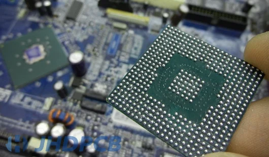
BGA reballing involves removing defective or oxidized solder balls from a BGA package and attaching fresh ones, restoring the component's functionality for reinstallation. This process is integral to the prototype PCB rework process, particularly when initial soldering prototypes reveals issues like ball detachment or bridging. In prototype stages, where small batch sizes limit economies of scale, reballing prevents the need for full board respins, saving both time and resources. Electric engineers rely on it to troubleshoot thermal mismatches or handling errors common in early builds. Without proper reballing, prototypes risk cascading failures that compromise signal integrity and mechanical reliability.
The relevance intensifies with shrinking pitch sizes in modern BGAs, demanding precision beyond standard soldering prototypes. Rework process efficiency directly impacts prototype validation cycles, enabling quicker design refinements.
Technical Principles Behind BGA Reballing
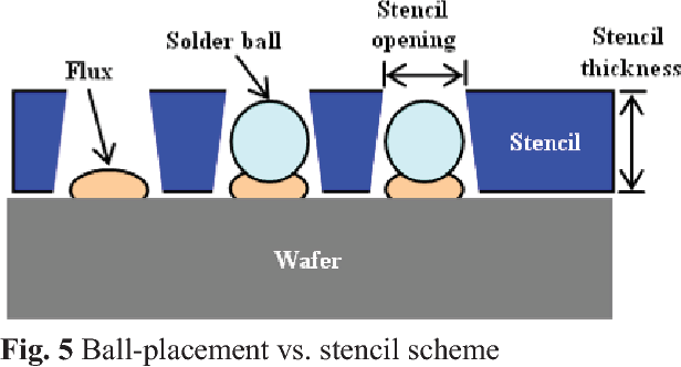
The core mechanism of BGA reballing hinges on controlled thermal profiling to melt and attach solder spheres without damaging the package substrate or underlying laminate. Solder balls, typically eutectic or lead-free alloys, must match the original metallurgy to avoid intermetallic brittleness during reflow. Flux application facilitates wetting, while stencils or fixtures ensure precise ball placement aligned to the BGA footprint. Heat is applied via convection or infrared, ramping gradually to prevent warpage, a common pitfall in prototype PCB rework.
Adhesion relies on surface preparation: pads are cleaned to expose clean copper, free of oxidation or residue. IPC-7711/7721 outlines specific procedures like fixture, paper carrier, or polyimide stencil methods, emphasizing process controls for repeatability. Thermal gradients must stay within tolerances to minimize voids, which could lead to head-in-pillow defects post-reinstallation.
Component flatness plays a pivotal role; excessive warpage disrupts ball transfer. Engineers monitor this through shadow moiré or laser profilometry before proceeding.
Step-by-Step Prototype PCB Rework Process for BGA Reballing
The prototype PCB rework process BGA reballing begins with diagnosis, often via X-ray or electrical testing to confirm ball failures. First, preheat the assembly to stabilize temperatures and reduce thermal shock. Remove the BGA using a rework station with top heater and bottom preheater, lifting it cleanly while preserving site pads.
Next, clean both the board pads and BGA underside with desoldering braid and isopropyl alcohol, inspecting for damage. For reballing, select a matching stencil with apertures corresponding to ball diameter and pitch. Apply tacky or no-clean flux to the BGA pads, align the stencil, and deposit solder balls using vibration or vacuum assist.
Reflow the balls in a controlled oven profile, peaking just above liquidus, then cool slowly. Post-reballing, inspect visually and via automated optical inspection (AOI). Reinstall the reballed BGA onto the prototype PCB, aligning fiducials precisely before final reflow. IPC-7095 provides guidance on BGA handling to ensure assembly integrity.
This sequence, when followed meticulously, integrates seamlessly into soldering prototypes workflows.
Best Practices for Reliable BGA Reballing in Prototypes
Maintain a moisture-controlled environment, baking components per manufacturer outlines to prevent popcorning during reflow. Use high-precision fixtures to combat misalignment, especially for fine-pitch BGAs under 0.5mm. Profile every rework cycle with thermocouples placed at critical zones: component center, edge, and board underside.
Opt for miniature solder balls to match prototype densities, verifying shear strength indirectly through process validation. Troubleshoot common issues like ball wicking by optimizing flux volume and stencil thickness. Document each step, including profiles and inspections, to refine future prototype PCB rework process BGA reballing iterations.
Incorporate nitrogen reflow to reduce oxidation, enhancing joint reliability. Train operators on IPC-A-610 criteria for post-rework acceptability, focusing on ball fillet and voiding limits.
Troubleshooting Common Challenges in BGA Reballing
Warpage often plagues prototypes due to CTE mismatches; mitigate by symmetric heating and fixturing the BGA during reballing. Bridged balls result from excess flux or poor stencil release, addressed by ultrasonic cleaning of stencils between uses. If voids appear post-reflow, check for insufficient preheat or flux activation.
Non-wetting pads signal contamination; aggressive plasma cleaning restores solderability without etching. For prototypes with multilayer stacks, monitor bottom-side temperatures to avoid delamination. Electrical opens after reinstallation point to pad lifting, necessitating site reinforcement before proceeding.
Systematic logging of failures refines the rework process, turning prototypes into robust pre-production units.
Inspection and Quality Assurance Post-Reballing
Visual inspection checks for uniform ball height and alignment, while X-ray verifies joint integrity without slicing samples. SAM (Scanning Acoustic Microscopy) detects subsurface voids in prototypes. Electrical testing confirms continuity across the grid array.
Adhere to class 3 criteria for high-reliability prototypes, ensuring no more than 25% voiding per IPC-A-610. Automated systems accelerate this for batch prototypes.
Conclusion
BGA reballing stands as a cornerstone of the prototype PCB rework process, empowering electric engineers to revive failed soldering prototypes efficiently. By mastering deballing, ball attachment, reflow, and inspection, teams minimize downtime and enhance design iterations. Integrating standards like IPC-7711/7721 ensures consistency, while best practices address real-world pitfalls. Ultimately, proficient BGA reballing prototype process elevates PCB prototypes from fragile experiments to reliable proofs-of-concept, streamlining the path to production.
FAQs
Q1: What are the main steps in the BGA reballing prototype process for PCB prototypes?
A1: The process starts with BGA removal and site cleaning, followed by deballing the component, fluxing pads, stencil placement of new solder balls, and controlled reflow. Post-reballing includes cleaning, inspection via X-ray, and reinstallation with precise alignment. This rework process ensures prototypes regain full functionality without full board replacement. Following IPC guidelines enhances reliability in soldering prototypes.
Q2: Why is BGA reballing essential in prototype PCB rework process?
A2: Prototypes often face early BGA failures from thermal stress or handling, making reballing a cost-effective fix over respinning boards. It restores solder joint integrity, preserving valuable design data and components. Electric engineers use it to troubleshoot iteratively, accelerating development. Proper execution per industry standards prevents reliability issues in subsequent builds.
Q3: How do you prevent common defects during rework process BGA reballing?
A3: Control thermal profiles to avoid warpage, use precise stencils for ball alignment, and bake components to eliminate moisture. Clean pads thoroughly and inspect incrementally with AOI or X-ray. Nitrogen atmospheres reduce oxidation. These practices, aligned with IPC-7095, ensure high-yield repairs in PCB prototypes.
Q4: When should electric engineers opt for BGA reballing over component replacement in prototypes?
A4: Choose reballing for salvageable packages with isolated ball damage, especially scarce or expensive parts in prototypes. It's ideal when board sites are intact and quick turnaround is needed. Avoid if substrate warpage exceeds limits or multiple rows are compromised. This targeted rework process optimizes prototype PCB workflows.
References
IPC-7711/7721D — Rework, Modification and Repair of Electronic Assemblies. IPC, 2024
IPC-7095E — Design and Assembly Process Implementation for Ball Grid Arrays (BGAs). IPC, 2024
IPC-A-610J — Acceptability of Electronic Assemblies. IPC, 2020