Introduction
High-Tg PCBs (Tg ≥170 °C) are no longer optional in aerospace, automotive, and high-reliability industrial electronics. Reliability is built layer by layer through correct material selection, controlled processing, and rigorous verification. Even a single missed bake cycle or insufficient desmear can turn a 180 °C Tg laminate—one of the most robust types of PCBs—into an early field failure.

Critical Material Properties That Determine Real-World Reliability
| Property | Mid-Tg FR-4 (140 °C) | Reliable High-Tg (≥175 °C) | Impact on Reliability |
|---|---|---|---|
| Tg (DSC midpoint) | 135–145 °C | 175–185 °C | Prevents resin softening during reflow |
| T260 (with Cu cladding) | 10–20 min | ≥60 min | Delamination resistance |
| T288 (with Cu cladding) | <5 min | ≥20 min | Measles/blister resistance |
| CTEz below Tg | 80–100 ppm/°C | 45–65 ppm/°C | Reduces via barrel stress |
| Td (5 % weight loss) | 310–330 °C | ≥360 °C | Survives multiple 270 °C reflow |
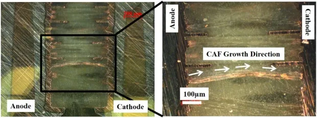
| CAF resistance (1000 h) | Marginal | >1500 V spacing | Prevents conductive filament growth |
All values measured per IPC-TM-650 test methods.
Common High-Tg Failure Modes and Their Root Causes
| Failure Mode | Typical Symptom | Primary Root Cause | Prevention Method |
|---|---|---|---|
| Corner via crack | Open after 500–1000 cycles | CTEz >70 ppm/°C + insufficient hole-wall texture | Use 180 °C Tg + plasma desmear |
| Pad cratering | Lifted BGA pad | Resin brittleness + high filler content | Select moderate-fill 175–180 °C systems |
| Delamination after reflow | Layer separation at inner copper | Moisture >0.1 % before lamination | 12 h 125 °C pre-bake + vacuum press |
| Conductive anodic filament | Short between biased holes | Inadequate resin cure + ionic contamination | Extended permanganate + plasma cycle |
| Measles/blistering | White spots after T288 | Incomplete cross-linking | Full 195 °C cure dwell in lamination |
Design-for-Reliability Rules Specific to High-Tg Materials
- Limit copper-free areas >25 × 25 mm to prevent resin shrinkage cracks
- Use teardrop pads and anchor spurs on all vias ≥0.3 mm
- Maintain ≤8:1 aspect ratio for microvias in 180 °C Tg stacks
- Specify minimum 20 µm hole-wall texture after desmear (SEM verification)
- Keep resin content 55–65 % in prepreg to avoid brittleness
Suggested Reading: Design Considerations for High Tg PCBs: A Comprehensive Checklist
Manufacturing Quality Control Points That Prevent 99 % of High-Tg Failures
Incoming Material Verification
- Measure Tg, T260, T288 on every lot using IPC-TM-650 2.4.24
- Reject lots showing T288 <15 min (phenolic-cured) or <20 min (multifunctional)
Pre-Lamination Baking
- 8–16 h at 120–130 °C to <0.08 % moisture (weight loss method)
- Vacuum storage immediately after baking
Desmear and Metallization
- Plasma cycle (CF4/O2) + alkaline permanganate + neutralizer
- Minimum 20 µm etch-back on glass bundles (cross-section check every panel)
Lamination Profile
- Pressure: 450–550 psi for 175–185 °C Tg systems
- Peak temperature dwell: minimum 60 min above 180 °C
- Cooling rate: ≤2.5 °C/min between 150 °C and 100 °C
Post-Lamination Inspection
- Acoustic microscopy on 100 % of Class 3 panels
- Thermal stress 288 °C/10 s float on every lot (IPC-TM-650 2.6.8)
Reliability Testing That Actually Predicts Field Life
| Test | Standard | Acceptance for High-Reliability High-Tg |
|---|---|---|
| Interconnect Stress Test (IST) | IPC-TM-650 2.6.26 | ≥600 cycles preconditioned + test |
| Highly Accelerated Thermal Shock | OEM-specific | 1000 cycles −55/+150 °C, ΔR <3 % |
| T300 (with Cu) | IPC-TM-650 2.4.24.1 | ≥60 min no delamination |
| CAF (100 V, 85 °C/85 %RH) | IPC-TM-650 2.6.25 | >1000 h no filament at 0.5 mm spacing |
| Reflow simulation | 6× 270 °C peak (JEDEC 22-A104) | No measles, blistering, or pad lift |
Conclusion
Mastering high tg PCB reliability requires treating 170–185 °C materials as completely different from standard FR-4. Every step from incoming lot verification through plasma desmear, controlled lamination, and mandatory IST testing directly determines whether the board survives 10 years at 150 °C or fails in the first 1000 hours. When material properties, processing discipline, and verification standards align, high-Tg boards consistently exceed the toughest aerospace and automotive lifetime requirements.
FAQs
Q1: What is the single biggest cause of high-Tg PCB field failures?
A1: Insufficient hole-wall desmear leading to corner via cracks after 500–1500 thermal cycles. Plasma + extended permanganate is mandatory for 175 °C+ materials.
Q2: Can a 170 °C Tg board be used if T288 exceeds 20 minutes?
A2: Yes, many automotive Grade 1 applications successfully use 170–175 °C Tg when T288 ≥20 min and CTEz ≤60 ppm/°C. T288 is often a better reliability predictor than Tg alone.
Q3: How do you verify high-Tg PCB quality control in production?
A3: 100 % acoustic microscopy on Class 3 lots, daily cross-section for desmear texture ≥20 µm, and IST coupons on every panel are industry best practice.
Q4: Does higher filler content always improve high-Tg PCB reliability?
A4: No. Excessive filler (>65 %) reduces resin toughness and increases pad cratering risk. Optimal reliability occurs at 50–60 % filler with CTEz 45–55 ppm/°C.
References
IPC-4101E — Specification for Base Materials for Rigid and Multilayer Printed Boards. IPC, 2017.
IPC-TM-650 2.4.24 — Glass Transition Temperature and Z-Axis Thermal Expansion. IPC, current version.
IPC-TM-650 2.4.24.1 — Time to Delamination (T260, T288, T300). IPC, current version.
IPC-TM-650 2.6.8 — Thermal Stress, Plated-Through Holes. IPC, current version.
IPC-TM-650 2.6.25 — Conductive Anodic Filament (CAF) Resistance. IPC, current version.
IPC-TM-650 2.6.26 — Interconnect Stress Testing (IST). IPC, current version.
IPC-6012E — Qualification and Performance Specification for Rigid Printed Boards. IPC, 2020.


