Introduction
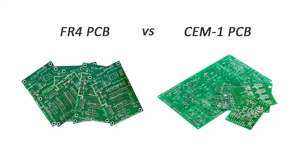
In the world of printed circuit board manufacturing, material selection plays a critical role in determining the performance, reliability, and cost-effectiveness of the final product. CEM-1 and FR-4 stand out as two widely used laminate materials, each suited to specific project needs. This CEM-1 PCB vs FR-4 comparison explores their differences to help electrical engineers make informed decisions during the design phase. Understanding these materials ensures compliance with industry standards and optimal factory outcomes. Factory-driven insights reveal that choosing the wrong substrate can lead to issues like warpage, delamination, or premature failure in assembly processes.
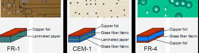
Understanding CEM-1 and FR-4 Materials
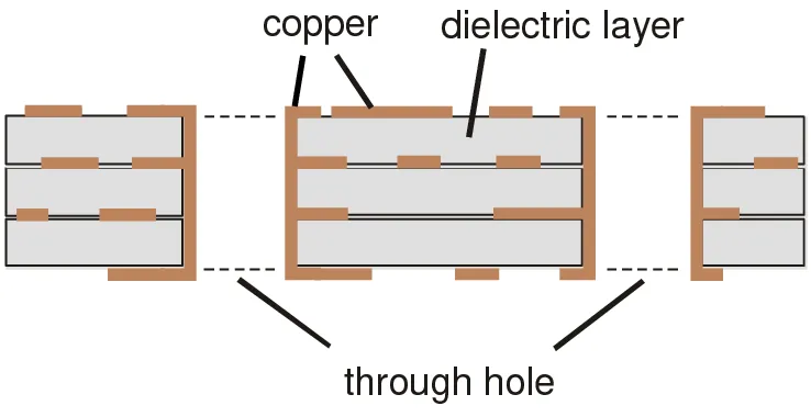
CEM-1, or Composite Epoxy Material 1, consists of a core made from cellulose paper reinforced with woven glass fabric on the outer surfaces, all impregnated with flame-retardant epoxy resin. This construction makes it a cost-effective option primarily for simpler board designs. In contrast, FR-4 features a uniform structure of woven fiberglass cloth fully impregnated with epoxy resin, providing robustness for demanding applications. Both materials meet basic flame-retardancy requirements, but their internal compositions dictate distinct processing behaviors in the factory. Engineers must consider these foundational differences when evaluating FR-4 alternative PCB materials.
Composition and Structure Differences
The paper-based core in CEM-1 offers flexibility during punching operations, allowing for efficient high-volume production of single-sided boards. FR-4's all-glass reinforcement ensures dimensional stability across multiple layers, supporting complex routing and via formation. This structural variance affects drillability, with CEM-1 accommodating easier mechanical punching at elevated temperatures. Factory experience shows FR-4 requires precise routing to maintain hole quality in multilayer stacks. These traits influence overall manufacturability and yield rates.
Mechanical Properties Comparison
FR-4 demonstrates superior flexural and tensile strength, making it ideal for boards under mechanical stress or vibration. CEM-1 provides adequate strength for low-stress environments but exhibits greater fragility, necessitating careful handling during assembly. Warpage tendencies differ significantly, with CEM-1 more prone to bowing due to its hybrid core. Standards like IPC-A-600 guide acceptability criteria for these properties, ensuring boards meet mechanical integrity thresholds. In factory settings, this translates to FR-4's preference for automotive or industrial controls.
Electrical and Thermal Performance
FR-4 offers better dielectric strength and lower dissipation factors, supporting higher signal integrity in moderate-frequency circuits. CEM-1 delivers reliable insulation for basic low-frequency designs but falls short in high-density layouts. Thermally, FR-4 maintains stability through higher glass transition points, resisting deformation during soldering or operation. CEM-1 suits applications with moderate heat dissipation, as its thermal expansion mismatches copper more readily, potentially stressing joints. Compliance with IPC-4101 specifications verifies these characteristics for rigid boards.
CEM-1 PCB Advantages and Disadvantages
CEM-1 shines as an FR-4 alternative PCB material through its lower cost, often reducing material expenses in budget-sensitive projects. Its excellent machinability supports punching over routing, lowering tooling wear in mass production. Lighter weight aids in applications where mass matters, and good solderability facilitates straightforward assembly. However, CEM-1 PCB advantages come with trade-offs: higher moisture absorption risks reliability in humid conditions, and limited layer support restricts it to single-sided use. Mechanical weakness demands design adjustments, like even component distribution, to mitigate breakage. Factory insights highlight its viability only for non-critical, high-volume runs.
Typical CEM-1 PCB Applications
CEM-1 finds use in consumer electronics like remote controls, toys, and basic appliances where cost drives decisions. LED lighting circuits benefit from its balanced heat handling and affordability. Power supply modules and simple control panels leverage its single-layer simplicity. In industrial settings, relay boards or sensor interfaces employ CEM-1 for non-demanding tasks. These CEM-1 PCB applications prioritize economy over extreme durability, aligning with factory optimization for volume output. Designs avoid plated through-holes to maximize its strengths.
Where FR-4 Excels in Applications
FR-4 dominates in multilayer boards for telecommunications, computing, and automotive electronics requiring reliability. Its versatility handles high-layer counts and fine-pitch components effectively. Medical devices and industrial controls rely on FR-4's stability under thermal cycling. Factory production scales seamlessly for complex prototypes to high volumes. This positions FR-4 as the go-to for performance-critical projects.
PCB Material Selection Guide
Selecting between CEM-1 and FR-4 begins with assessing layer count: opt for CEM-1 in single-sided designs, reserving FR-4 for multilayers. Evaluate operating temperatures and thermal cycling; FR-4 prevails in elevated environments. Consider mechanical loads and environmental exposure, favoring FR-4 for vibration or humidity. Cost analysis weighs upfront savings against long-term reliability, with CEM-1 suiting prototypes or disposables. Reference IPC-6012 for qualification specs to ensure performance alignment. Prototype testing validates choices, focusing on warpage and solder joint integrity.
- Layer Count: Favor CEM-1 — Single-sided; Favor FR-4 — Multi-layer
- Cost Priority: Favor CEM-1 — High-volume, low-cost; Favor FR-4 — Performance-balanced
- Thermal Demands: Favor CEM-1 — Moderate; Favor FR-4 — High
- Mechanical Stress: Favor CEM-1 — Low; Favor FR-4 — High
- Moisture Exposure: Favor CEM-1 — Controlled; Favor FR-4 — Harsh
Best Practices for CEM-1 Implementation
Design CEM-1 boards with wide traces to accommodate potential expansion differences. Distribute components evenly to minimize stress concentrations. Bake boards prior to assembly to reduce moisture effects. Use copper pours for heat spreading in LED applications. Adhere to IPC-A-600 for visual and mechanical inspections post-fabrication. These steps enhance yield and reliability in factory processes.
Conclusion
The CEM-1 PCB vs FR-4 comparison underscores CEM-1's role as a viable FR-4 alternative for cost-driven, simple designs while FR-4 remains essential for robust applications. Weighing advantages like CEM-1's affordability against its limitations ensures project success. Factory-aligned choices, guided by standards, balance performance and economics. Electrical engineers benefit from structured evaluations to select materials that meet specs without compromise.
FAQs
Q1: What are the main CEM-1 PCB advantages and disadvantages compared to FR-4?
A1: CEM-1 offers lower cost and easier punching for single-sided boards, making it a strong FR-4 alternative PCB material in volume production. Disadvantages include reduced mechanical strength, higher moisture sensitivity, and limited thermal stability, restricting it from multilayer or high-heat uses. Factory standards like IPC-4101 confirm these traits for appropriate applications.
Q2: In what CEM-1 PCB applications does it outperform FR-4?
A2: CEM-1 excels in low-cost, single-layer designs such as LED drivers, remote controls, and power adapters where economy trumps complexity. Its lighter weight and machinability suit high-volume consumer goods. For these CEM-1 PCB applications, it provides reliable performance without FR-4's added expense.
Q3: How does this PCB material selection guide help choose between CEM-1 and FR-4?
A3: The guide evaluates factors like layers, temperature, cost, and environment to match needs precisely. CEM-1 fits budget single-sided projects, while FR-4 supports demanding multilayers. Standards compliance ensures manufacturability, aiding engineers in optimized decisions.
Q4: Is CEM-1 a suitable FR-4 alternative for all projects?
A4: No, CEM-1 serves as an FR-4 alternative only for simple, cost-sensitive single-layer boards with moderate requirements. It lacks FR-4's multilayer capability and thermal robustness for high-reliability uses. Assess project specs via IPC guidelines for best fit.
References
IPC-4101 — Specification for Base Materials for Rigid and Multilayer Printed Boards. IPC, 2017
IPC-6012E — Qualification and Performance Specification for Rigid Printed Boards. IPC, 2015
IPC-A-600K — Acceptability of Printed Boards. IPC, 2020