What Role Do Conformal Coatings Play in High-Frequency PCB Performance?
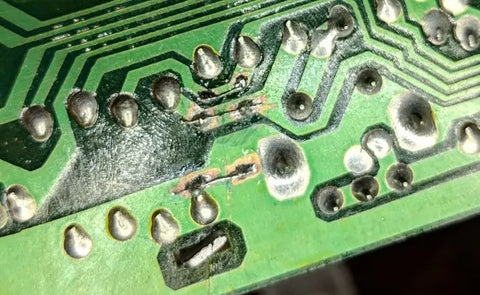
Conformal coating is a specialized, thin protective layer applied to Printed Circuit Boards (PCBs) to shield them from adverse environmental factors such as moisture, dust, chemical exposure, and extreme temperatures. For high-frequency PCBs—which are integral to advanced applications like wireless communication, sophisticated radar systems, and cutting-edge 5G technology—this protective barrier is not just beneficial but absolutely critical. However, unlike standard PCBs, high-frequency designs operate at gigahertz (GHz) frequencies, where even minor alterations in material properties can lead to significant signal degradation.
The core challenge when applying conformal coating to high-frequency PCBs lies in achieving an optimal balance between robust environmental protection and uncompromised electrical performance. An ill-chosen or improperly applied coating can inadvertently modify the board's electrical characteristics, potentially causing signal loss or introducing unwanted interference. Consequently, for engineers specializing in RF and microwave circuits, a thorough understanding of how a coating impacts the dielectric constant, signal integrity, and insertion loss is not merely advantageous but essential for successful design.
Key Technical Considerations for High-Frequency Conformal Coatings
Selecting an appropriate conformal coating for high-frequency applications demands careful evaluation of several technical attributes. Let's delve into these factors to guide you toward an informed decision.
1. Dielectric Constant of Conformal Coating
The conformal coating dielectric constant is a measure of a material's ability to store electrical energy within an electric field. In the context of the high-frequency PCB, a coating with an elevated dielectric constant can cause a detrimental slowdown in signal propagation speed and lead to critical impedance mismatches. Therefore, for RF circuits, the ideal coating should possess a low dielectric constant—preferably in the range of 2 to 3—to minimize these negative effects.
For illustration, silicone-based coatings typically exhibit a dielectric constant between 2.5 and 3.5, which often makes them a favored choice for many high-frequency designs. In contrast, some epoxy coatings can have values exceeding 4, which could severely impede signal speeds in circuits operating at 5 GHz or higher. Prioritizing a coating with a stable dielectric constant across a broad frequency spectrum is key to ensuring consistent and reliable performance.
2. Impact on Signal Integrity
Conformal coating signal integrity refers to the coating's capacity to preserve the quality and fidelity of electrical signals as they traverse the PCB. High-frequency signals are exquisitely sensitive to distortions that arise from the surrounding material properties. A coating that inadvertently introduces parasitic capacitance or inductance can degrade signal integrity, resulting in errors during data transmission.
To safeguard signal integrity, it is advisable to select ultra-thin coatings that adhere tightly and uniformly to the board’s surface, avoiding any unnecessary bulk. Certain advanced coatings are specifically engineered for high-speed circuits, offering minimal interference even at frequencies surpassing 10 GHz. Rigorous testing of the coated board under real-world conditions, such as temperature cycling between -40°C and 85°C, can provide valuable insights into its long-term impact on signal behavior.
3. Insertion Loss and Coating Thickness
Conformal coating insertion loss quantifies the reduction in signal strength as an electrical signal passes through a coated PCB. This signal attenuation becomes more pronounced at higher frequencies, where even a slight increase in coating thickness can cause signals to be absorbed or scattered. For example, a coating thickness of 25 micrometers might result in negligible loss at 1 GHz but could translate into a measurable 0.5 dB loss at 10 GHz.
To mitigate insertion loss, designers should opt for coatings characterized by low loss tangent values (which indicate lower energy dissipation) and ensure they are applied in thin, consistent layers. Parylene coatings, for instance, can be applied in layers as fine as 10 micrometers, rendering them exceptionally well-suited for minimizing signal loss in sensitive RF designs. Automated application techniques, such as vapor deposition, are recommended to guarantee uniform coverage without excessive material buildup.
4. Environmental Protection Without Performance Compromise
High-frequency PCBs often function in challenging environments, from outdoor antenna arrays exposed to precipitation to industrial systems contending with corrosive chemical fumes. Consequently, a conformal coating must offer robust protection against these conditions while simultaneously avoiding any alteration of the board's critical electrical properties. Coatings with a high dielectric strength—typically exceeding 1000 volts per mil—are essential for preventing unwanted current leakage, while low moisture absorption rates ensure performance stability even in highly humid operating conditions.
Exploring Types of Conformal Coatings for High-Frequency PCBs
Not all conformal coatings are created with the same properties or for the same applications. Let’s examine the most common types and evaluate their suitability for high-frequency use.
Coating Options
● 1. Silicone Coatings: These coatings are valued for their flexibility and exceptional thermal stability, capable of withstanding temperatures ranging from -55°C to 200°C. With a dielectric constant typically between 2.5 and 3.5 and a moderate loss tangent, silicones are a suitable option for many RF circuits. However, it's crucial to control their application thickness precisely, as thicker layers can contribute to increased insertion loss.
● 2. Parylene Coatings: Parylene is applied via a unique vapor deposition process, resulting in an ultra-thin and supremely uniform layer. Its dielectric constant, approximately 2.6 to 3.1, ensures minimal impact on signal integrity, making it one of the most highly recommended conformal coatings for sensitive RF circuits. Parylene also offers superior resistance to moisture and chemicals, although its specialized application process can incur higher costs and complexity.
● 3. Acrylic Coatings: Acrylic coatings are known for their ease of application and reworkability, providing adequate protection against humidity and dust. However, their generally higher dielectric constant (often above 3.5) and increased loss tangent make them less ideal for high-frequency PCBs operating beyond 5 GHz. They are typically better suited for lower-frequency or mixed-signal designs.
● 4. Urethane Coatings: Urethane coatings offer robust chemical resistance and excellent durability. Nevertheless, they tend to possess higher dielectric constants (around 4 or more), which renders them less suitable for high-frequency applications where minimizing signal loss is a primary concern. They are often chosen for demanding, rugged environments where chemical exposure is the dominant threat.
Guidelines for Selecting the Optimal Conformal Coating for RF Circuits
The process of choosing the best conformal coating for RF circuits is highly dependent on your specific application’s performance and environmental requirements. Follow these structured steps to effectively narrow down your options:
Selection Process
● Evaluate Frequency Range: Precisely determine the operating frequency range of your PCB. For circuits functioning above 5 GHz, prioritize coatings with exceptionally low dielectric constants and minimal insertion loss, such as Parylene or very thin silicone applications.
● Assess Environmental Needs: Identify all potential environmental hazards your PCB will encounter. For outdoor RF applications, select a coating that offers superior resistance to moisture, humidity, and UV radiation.
● Test for Signal Impact: Before commencing full-scale production, apply the chosen coating to a prototype board. Use specialized tools like a vector network analyzer to accurately measure signal integrity. Pay close attention to any changes in impedance or signal loss at your target operating frequencies.
● Consider Application Method: Be aware that certain coatings, such as Parylene, necessitate specialized equipment and processes for their application. Ensure that your manufacturing or assembly process can appropriately accommodate the chosen coating type.
Best Practices for Applying Conformal Coating to High-Frequency PCBs
The precise application of conformal coating to high-frequency PCBs is critical to prevent performance degradation. Adhering to these practical tips will help ensure optimal results.
Application Tips
● Mask Critical Areas: Employ masking tape or specialized removable gels to protect connectors, antenna connection points, and other sensitive components from unintended coating buildup, which could interfere with signal transmission or mechanical fit.
● Control Thickness Uniformity: Strive for a consistent and uniform coating thickness, typically between 25 to 50 micrometers, for most coating types. Excessively thick layers can exacerbate insertion loss, particularly at frequencies exceeding 10 GHz.
● Utilize Automated Methods: Automated spray or vapor deposition systems are highly recommended as they provide significantly more consistent and even coverage compared to manual brushing, thereby reducing the risk of uneven application or excessive material accumulation.
● Proper Curing Procedures: Strictly adhere to the manufacturer’s specified curing guidelines. Improper curing can lead to residual solvents or incomplete hardening, which can adversely affect the coating's dielectric properties and long-term performance.
Addressing Challenges in High-Frequency Conformal Coating Applications
Even with the most appropriate coating selection, specific challenges can arise when applying conformal coatings to high-frequency PCBs. Here’s how to effectively mitigate these common issues:
Common Challenges and Solutions
● Challenge: Signal Loss Due to Coating Thickness:
○ Solution: Opt for coatings that can be applied in ultra-thin layers, and conduct thorough testing across various application thicknesses to identify the optimal balance between environmental protection and electrical performance.
● Challenge: Dielectric Constant Variations:
○ Solution: Collaborate closely with coating suppliers to obtain detailed material data sheets. Select products that demonstrate stable dielectric properties consistently across your PCB's entire operating frequency range.
● Challenge: Rework and Repair Difficulties:
○ Solution: Choose coatings that permit easy soldering through or can be safely and effectively removed without causing damage to the underlying PCB or its critical signal paths.
Future Innovations in Conformal Coating for High-Frequency PCBs
As electronic technology continues its rapid advancement, so too do the materials and methodologies employed in conformal coating. Emerging trends include the development of cutting-edge nanotechnology-based coatings, which are designed to offer even lower dielectric constants and reduced loss tangents, making them ideally suited for next-generation 5G and 6G applications. Furthermore, the industry is seeing increased adoption of eco-friendly coatings with significantly reduced volatile organic compound (VOC) content, providing high performance with a lower environmental footprint.
Another exciting area of development is the integration of electromagnetic absorbing coatings. These innovative materials not only provide physical protection for the PCB but also actively reduce electromagnetic interference (EMI) within high-frequency designs. Such advancements promise to further enhance the reliability, efficiency, and overall performance of RF circuits in the most demanding applications.
Concluding Thoughts: Achieving Optimal Protection and Performance with the Right Coating
For high-frequency PCBs, conformal coating transcends its role as a mere protective layer; it stands as a critical design element that can fundamentally determine the success or failure of a circuit’s performance. By meticulously focusing on key parameters such as the conformal coating dielectric constant, its impact on signal integrity, and its contribution to insertion loss, engineers can effectively select the optimal conformal coating for RF circuits—one that adeptly fulfills both rigorous environmental and precise electrical requirements.
Whether your projects involve sophisticated wireless communication systems, advanced aerospace radar, or high-speed digital designs, the correct coating choice ensures your PCB can withstand harsh conditions without compromising signal quality. It is imperative to dedicate sufficient time to evaluate all available options, thoroughly test prototypes, and apply coatings with meticulous precision. By following these essential steps, you will successfully achieve reliable, high-performing PCBs that are perfectly tailored to meet the exacting demands of modern technology.