Introduction
Electronics assembly forms the backbone of creating functional devices, transforming raw components and printed circuit boards into reliable systems. For electronic hobbyists, understanding the nuances of assembly, inspection, and potential failure points is essential to build durable projects. This process involves meticulous attention to soldering, component placement, and quality checks to ensure reliability. Failures in assembly can lead to costly rework or complete device breakdowns, impacting both time and resources. This article explores the critical aspects of electronics assembly, focusing on inspection techniques, reliability factors, and common causes of failure during manufacture. By grasping these concepts, hobbyists can enhance their skills and produce electronics that withstand real-world use. Let’s dive into the key elements that define successful assembly and how to avoid pitfalls.
What Is Electronics Assembly and Why It Matters
Electronics assembly refers to the process of integrating components onto a printed circuit board to create a functional electronic device. This includes tasks like soldering, mounting components, and connecting circuits to ensure proper operation. For hobbyists, assembly is often a hands-on endeavor, requiring precision and patience to achieve reliability. The importance of this process lies in its direct impact on device performance. Poor assembly can result in failures such as short circuits, open connections, or thermal stress, rendering a project useless. Reliable assembly ensures that electronics function as intended, whether it’s a simple LED circuit or a complex microcontroller setup. By prioritizing quality during manufacture, hobbyists can avoid frustrating setbacks and build confidence in their creations. Understanding assembly also helps in troubleshooting issues when failures occur.
Technical Principles of Electronics Assembly and Failure Causes
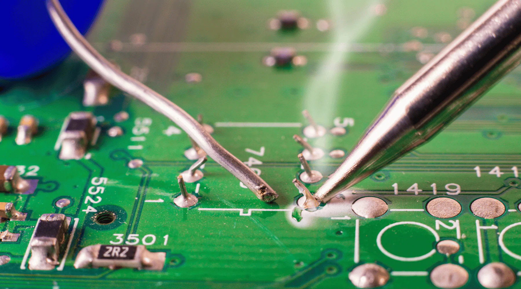
Electronics assembly relies on several technical principles to ensure components work together seamlessly. One fundamental aspect is the soldering process, which creates electrical and mechanical connections between components and the board. If solder joints are weak or improperly formed, they can lead to open circuits or intermittent failures. Temperature control during soldering is critical, as excessive heat can damage components or cause thermal stress, leading to cracks over time.
Another key principle is component placement accuracy. Misaligned components can disrupt signal paths or cause short circuits, especially in densely populated boards. This is often a challenge in surface mount technology, where tiny parts require precise positioning. Additionally, contamination from flux residues or dust can degrade reliability by causing corrosion or unintended conductivity.
Failures in electronics assembly often stem from specific causes. Poor solder joint formation, due to insufficient heat or incorrect solder alloy, is a common issue. Mechanical stress from improper handling during manufacture can also weaken connections. Environmental factors, such as humidity or temperature fluctuations, may induce failures like corrosion or material expansion. Electrostatic discharge is another risk, potentially damaging sensitive components if proper precautions are not taken. Understanding these principles and failure causes allows hobbyists to take preventive measures during assembly.
Inspection Techniques for Ensuring Reliability
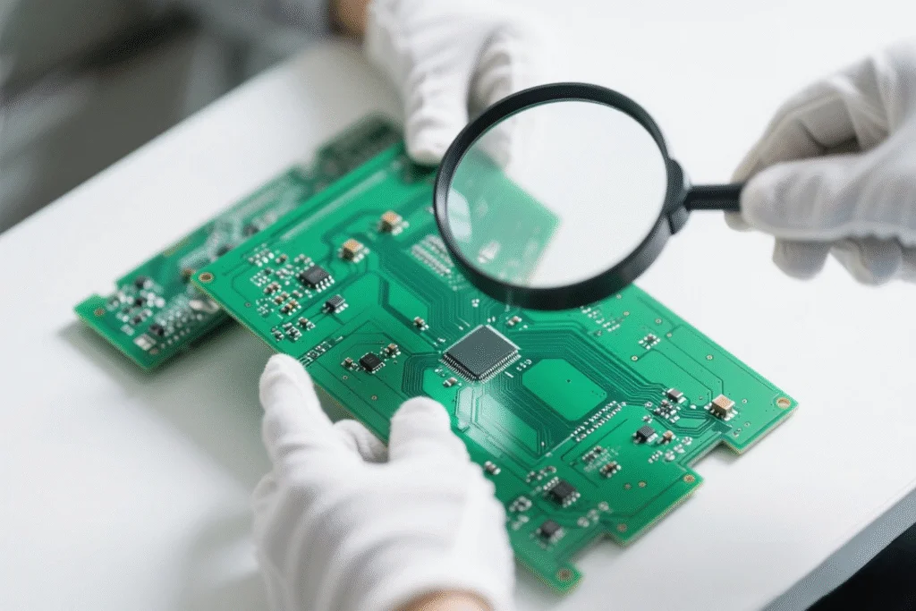
Inspection plays a vital role in electronics assembly by identifying defects before they lead to failure. For hobbyists, visual inspection is the most accessible method. This involves examining solder joints for uniformity, checking for visible cracks, and ensuring components are correctly placed. A magnifying glass or microscope can help spot tiny flaws that are easy to miss with the naked eye.
Beyond visual checks, functional testing is crucial to verify reliability. This means powering up the assembled board and testing for expected behavior, such as correct voltage levels or signal outputs. Simple tools like multimeters can measure continuity and detect open or short circuits. For more advanced hobbyists, in-circuit testing can pinpoint specific component issues by probing individual parts of the circuit.
Automated inspection methods, though less common in hobbyist settings, are worth mentioning for their precision. Techniques like automated optical inspection, as guided by industry standards, use cameras to detect soldering defects or misplacements. While such tools may be out of reach for most hobbyists, understanding their principles can inspire manual checks with similar attention to detail. Regular inspection during and after assembly helps catch issues early, ensuring long-term reliability of electronics projects.
Practical Solutions and Best Practices for Assembly
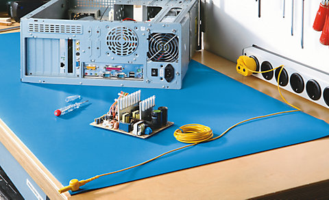
Achieving reliability in electronics assembly requires adopting practical solutions and best practices. Start with a clean workspace to prevent contamination. Dust or debris can interfere with solder joints, so keep the area free of clutter. Use proper tools, such as a temperature-controlled soldering iron, to avoid overheating components. A soldering tip suited to the component size ensures precise application of heat.
Follow a systematic approach during assembly. Place components in order of size, starting with smaller parts to avoid obstructing access to tighter spaces. Double-check component orientation, especially for polarized parts like diodes or capacitors, to prevent circuit failures. Applying solder flux can improve joint quality by reducing oxidation during the process.
Adhering to recognized guidelines enhances manufacture quality. For instance, standards like IPC-A-610, which outlines acceptability criteria for electronic assemblies, provide benchmarks for solder joint appearance and component placement. While hobbyists may not have direct access to such documents, familiarizing themselves with summarized guidelines from technical resources can be beneficial. After assembly, clean the board with isopropyl alcohol to remove flux residues that might cause corrosion over time.
Finally, protect against electrostatic discharge by using an anti-static wrist strap or mat. This prevents damage to sensitive components during handling. Testing the board at each stage of assembly helps identify issues early, saving time on rework. By integrating these practices, hobbyists can significantly boost the reliability of their electronics projects.
Common Failure Modes and Troubleshooting Tips
Electronics assembly failures often manifest in predictable ways, and knowing how to troubleshoot them is invaluable for hobbyists. One frequent issue is a non-functional board due to poor solder joints. If a circuit fails to work, inspect joints for cracks or incomplete connections. Reheating and adding a small amount of fresh solder can often resolve this. Ensure the soldering iron is at the correct temperature to avoid further damage.
Another common failure is short circuits caused by solder bridges between adjacent pads. Visually check for unintended solder connections and use a desoldering braid to remove excess material. Component misplacement or incorrect orientation also leads to failures. Verify each part against the schematic before powering on, as reversing a component can cause permanent damage.
Intermittent issues, where a device works sporadically, often point to loose connections or thermal stress. Gently wiggle components to check for movement, and reflow solder if needed. Environmental factors like moisture can cause corrosion, so store assembled boards in a dry place. For complex failures, systematically test sections of the circuit with a multimeter to isolate the problem area. Keeping a log of assembly steps and test results can help track down recurring issues, improving future reliability.
Conclusion
Electronics assembly is a skill that blends precision, patience, and technical knowledge to create reliable devices. For hobbyists, mastering inspection techniques and understanding failure causes are key to successful projects. By focusing on proper soldering, accurate component placement, and thorough testing, the reliability of assembled electronics can be greatly enhanced. Adopting best practices, such as maintaining a clean workspace and following industry guidelines, further reduces the risk of failure during manufacture. Troubleshooting common issues like poor solder joints or short circuits equips hobbyists to address problems effectively. Ultimately, a commitment to quality at every step of assembly ensures that electronics not only function as intended but also stand the test of time. Keep learning and refining these skills to elevate your craft in this rewarding field.
FAQs
Q1: What are common causes of failure in electronics assembly for hobbyists?
A1: Failures in electronics assembly often arise from poor solder joints, component misplacement, or short circuits due to solder bridges. Environmental factors like humidity can cause corrosion, while electrostatic discharge may damage sensitive parts. Inspecting joints visually and testing with a multimeter can help identify issues early. Following proper soldering techniques and using protective measures like anti-static gear greatly reduces these risks during manufacture.
Q2: How can I improve reliability in my electronics projects?
A2: To boost reliability, use a clean workspace to avoid contamination and a temperature-controlled soldering iron for precise heat application. Follow a systematic assembly process, double-check component orientation, and test at each stage. Cleaning flux residues after soldering prevents corrosion. Adhering to guidelines from standards like IPC-A-610, even informally, helps ensure quality connections and long-lasting electronics performance.
Q3: What inspection methods work best for electronics assembly at home?
A3: Visual inspection with a magnifying glass is effective for spotting solder joint defects or misaligned components in electronics assembly. Functional testing with a multimeter checks for continuity and short circuits. Test the board after each major step to catch issues early. While advanced tools are less accessible, manual checks inspired by automated optical inspection principles can enhance attention to detail for hobbyists.
References
IPC-A-610H — Acceptability of Electronic Assemblies. IPC, 2020.
IPC-J-STD-001H — Requirements for Soldered Electrical and Electronic Assemblies. IPC, 2020.


