Introduction
FR-4 is a widely used material in printed circuit board (PCB) manufacturing, known for its balance of cost, durability, and electrical performance. As the foundation for countless electronic devices, mastering assembly techniques for FR-4 PCBs is essential for electrical engineers. This guide explores key methods including FR-4 PCB SMT assembly, FR-4 PCB through-hole assembly, and FR-4 PCB mixed technology assembly. It also covers FR-4 PCB soldering techniques and FR-4 PCB component placement strategies. Whether you are designing consumer electronics or industrial systems, understanding these processes ensures reliability and efficiency. The following sections provide detailed insights into the principles, best practices, and practical solutions for assembling FR-4 PCBs, tailored to the needs of technical professionals seeking to optimize their projects.
What Is FR-4 PCB Assembly and Why It Matters
FR-4, a flame-retardant epoxy laminate, serves as the standard substrate for most PCBs due to its mechanical strength and electrical insulation properties. Assembly of the FR-4 PCB involves attaching electronic components to the board using various techniques to create functional circuits. These methods include surface mount technology (SMT), through-hole technology (THT), and mixed technology approaches. The importance of proper assembly cannot be overstated, as it directly impacts the performance, durability, and manufacturability of electronic devices.
Poor assembly practices can lead to issues like weak solder joints, component misalignment, or thermal stress, resulting in failures. For electrical engineers, selecting the right technique for FR-4 PCB SMT assembly or FR-4 PCB through-hole assembly ensures that the final product meets design specifications. Additionally, understanding FR-4 PCB mixed technology assembly allows for combining the strengths of multiple methods, addressing diverse application needs from compact consumer gadgets to robust industrial equipment.
Technical Principles of FR-4 PCB Assembly Techniques
Surface Mount Technology (SMT) for FR-4 PCBs
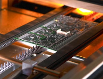
Surface mount technology involves placing components directly onto the surface of the PCB, typically using automated equipment. In FR-4 SMT PCB assembly, small components are mounted on pads with solder paste applied beforehand. The board then undergoes reflow soldering, where heat melts the paste to form secure connections. This method suits high-density designs, enabling smaller footprints and faster production. However, it requires precise control to avoid defects like tombstoning or insufficient solder.
Through-Hole Technology (THT) for FR-4 PCBs
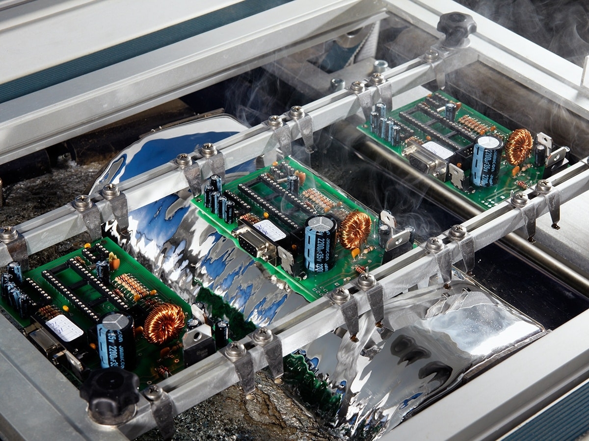
In FR-4 PCB through-hole assembly, components with leads are inserted into drilled holes on the board and soldered on the opposite side. This technique provides strong mechanical bonds, making it ideal for components under stress, such as connectors or large capacitors. While less common in miniaturized designs, THT remains relevant for applications needing durability. Manual soldering is often used for prototypes, though wave soldering automates the process for larger volumes.
Mixed Technology Assembly for FR-4 PCBs
FR-4 PCB mixed technology assembly combines SMT and THT on the same board. This approach leverages SMT for compact, lightweight components and THT for parts requiring robust connections. Managing mixed assemblies involves careful planning of soldering processes, as SMT components typically undergo reflow soldering first, followed by wave or manual soldering for THT parts. This method is common in complex devices where both space efficiency and mechanical strength are critical.
Soldering Techniques for FR-4 PCBs
FR-4 PCB soldering techniques vary based on the assembly method. Reflow soldering, used in SMT, involves applying solder paste, placing components, and heating the board in a controlled oven to melt the paste. Wave soldering suits THT, where the board passes over a molten solder wave to form joints. Hand soldering is practical for small-scale or rework tasks. Each technique requires adherence to thermal profiles to prevent damage to FR-4 material or components, as excessive heat can cause delamination or warpage.
Component Placement Strategies for FR-4 PCBs
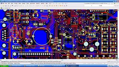
Effective FR-4 PCB component placement ensures functionality and manufacturability. Components must be positioned to minimize signal interference, optimize thermal dissipation, and facilitate assembly. For SMT, automated pick-and-place machines require precise design files to align parts accurately. In THT, placement considers lead insertion and soldering access. Mixed technology boards need strategic layouts to separate SMT and THT processes, reducing the risk of thermal or mechanical stress during assembly.
Practical Solutions and Best Practices for FR-4 PCB Assembly
Optimizing FR-4 PCB SMT Assembly
To achieve reliable FR-4 PCB SMT assembly, start with accurate stencil design for solder paste application. Ensure the stencil apertures match component pad sizes to avoid excess or insufficient paste. Use automated inspection systems to verify paste application before component placement. During reflow soldering, follow a thermal profile that gradually increases and decreases temperature to prevent thermal shock to the FR-4 material. Post-assembly, inspect for defects like bridging or cold joints using visual or automated optical inspection methods as outlined in industry standards.
Enhancing FR-4 PCB Through-Hole Assembly
For FR-4 PCB through-hole assembly, select drill sizes that match component leads to prevent loose fits or damage during insertion. When using wave soldering, adjust the conveyor speed and solder temperature to ensure proper wetting without overheating the board. Preheating the PCB can reduce thermal stress on the FR-4 substrate. For manual soldering, use a temperature-controlled iron and apply flux to improve solder flow, ensuring strong joints without damaging surrounding areas.
Managing FR-4 PCB Mixed Technology Assembly
In FR-4 PCB mixed technology assembly, sequence the processes to protect components from excessive heat. Assemble SMT components first using reflow soldering, then add THT components with wave or hand soldering. Use fixtures to hold components in place during multiple soldering cycles. Design the board layout to group SMT and THT components separately when possible, minimizing interference. Regularly inspect solder joints for consistency, especially at transitions between assembly types, to ensure reliability across the board.
Mastering FR-4 PCB Soldering Techniques
Successful FR-4 PCB soldering techniques depend on controlling heat and material interactions. For reflow soldering, adhere to profiles specified in standards like IPC/JEDEC J-STD-020E to match component and board tolerances. In wave soldering, monitor solder bath composition to prevent contamination that could weaken joints. When hand soldering, use the appropriate tip size and maintain clean tools to avoid introducing defects. Always apply flux to enhance wetting and remove oxides, ensuring durable connections on FR-4 PCBs.
Improving FR-4 PCB Component Placement
Effective FR-4 PCB component placement starts with design software that supports design for manufacturability principles. Place heat-sensitive components away from high-power elements to avoid thermal issues. Orient components consistently to simplify automated assembly and reduce errors. For mixed technology boards, ensure clearance around THT components for soldering access. Verify placement accuracy with automated optical inspection after assembly to catch misalignments early. Following guidelines from standards like IPC-A-600K helps maintain acceptable quality levels during production.
Suggested Reading: High-Performance PCB Assembly: Key Design Considerations 2026
Troubleshooting Common Issues in FR-4 PCB Assembly
Assembly of FR-4 PCBs can encounter challenges that affect performance. In SMT, tombstoning occurs when one end of a component lifts during reflow soldering, often due to uneven heating or pad design. Correct this by balancing pad sizes and optimizing the reflow profile. For THT, insufficient solder fill in holes can weaken connections, typically caused by poor wetting or low preheat. Address this by adjusting preheat settings and ensuring clean leads. In mixed technology assemblies, thermal stress from multiple soldering cycles may cause FR-4 warpage. Mitigate this by using controlled heating and cooling phases. Regular inspection using methods described in IPC-A-600K ensures early detection of such defects, allowing for timely corrective actions.
Conclusion
Mastering FR-4 PCB assembly techniques is vital for electrical engineers aiming to produce reliable and efficient electronic devices. Whether focusing on FR-4 PCB SMT assembly for compact designs, FR-4 PCB through-hole assembly for durability, or FR-4 PCB mixed technology assembly for versatility, each method offers unique benefits and challenges. Implementing best practices in FR-4 PCB soldering techniques and FR-4 PCB component placement ensures high-quality outcomes. By adhering to established industry standards and addressing common issues through systematic troubleshooting, engineers can optimize their assembly processes. This comprehensive guide serves as a foundation for achieving excellence in FR-4 PCB projects, supporting innovation across various applications.
FAQs
Q1: What are the key challenges in FR-4 PCB SMT assembly?
A1: In FR-4 PCB SMT assembly, challenges include tombstoning, solder bridging, and component misalignment. These often stem from uneven heating, incorrect pad design, or improper solder paste application. Using precise stencils and adhering to thermal profiles as per industry standards can mitigate these issues. Regular inspection after reflow soldering helps identify defects early, ensuring reliable connections on the FR-4 substrate.
Q2: How does FR-4 PCB through-hole assembly differ from SMT?
A2: FR-4 PCB through-hole assembly involves inserting component leads into drilled holes and soldering them, offering strong mechanical bonds ideal for durable applications. In contrast, SMT places components directly on surface pads, suitable for compact designs. THT often uses wave or hand soldering, while SMT relies on reflow soldering. Each method suits different needs based on design goals and component types.
Q3: Why choose FR-4 PCB mixed technology assembly for complex designs?
A3: FR-4 PCB mixed technology assembly combines SMT and THT to balance space efficiency with mechanical strength in complex designs. SMT handles small, high-density components, while THT supports larger, stress-prone parts. This approach requires careful soldering sequence planning to avoid thermal damage. It is ideal for devices needing both compactness and robustness, ensuring versatility in functionality.
Q4: What are essential tips for FR-4 PCB soldering techniques?
A4: For effective FR-4 PCB soldering techniques, control heat to prevent damage to the board or components. Use appropriate thermal profiles for reflow soldering in SMT and adjust preheat for wave soldering in THT. Apply flux to improve wetting and clean tools regularly for hand soldering. Following standards like IPC/JEDEC J-STD-020E ensures consistent, high-quality solder joints across assembly processes.
References
IPC-6012E — Qualification and Performance Specification for Rigid Printed Boards. IPC, 2020.
IPC-A-600K — Acceptability of Printed Boards. IPC, 2020.
IPC/JEDEC J-STD-020E — Moisture/Reflow Sensitivity Classification for Nonhermetic Surface Mount Devices. JEDEC, 2014.
ISO 9001:2015 — Quality Management Systems. ISO, 2015.


