Introduction
Drilling holes and vias forms a foundational step in printed circuit board manufacturing, directly influencing signal integrity, reliability, and overall performance. Engineers face a critical decision between laser drilling and mechanical drilling, each offering distinct advantages based on project specifications. Laser drilling vs. mechanical drilling debates often center on factors like hole quality, production speed, cost analysis, and PCB thickness compatibility. This choice impacts not only fabrication efficiency but also compliance with industry performance standards. Understanding these methods helps procurement teams and designers select the optimal approach for high-density interconnects or standard multilayer boards. Factory insights reveal that mismatched drilling can lead to yield losses or rework, underscoring the need for informed decisions.
Understanding Mechanical Drilling in PCB Manufacturing
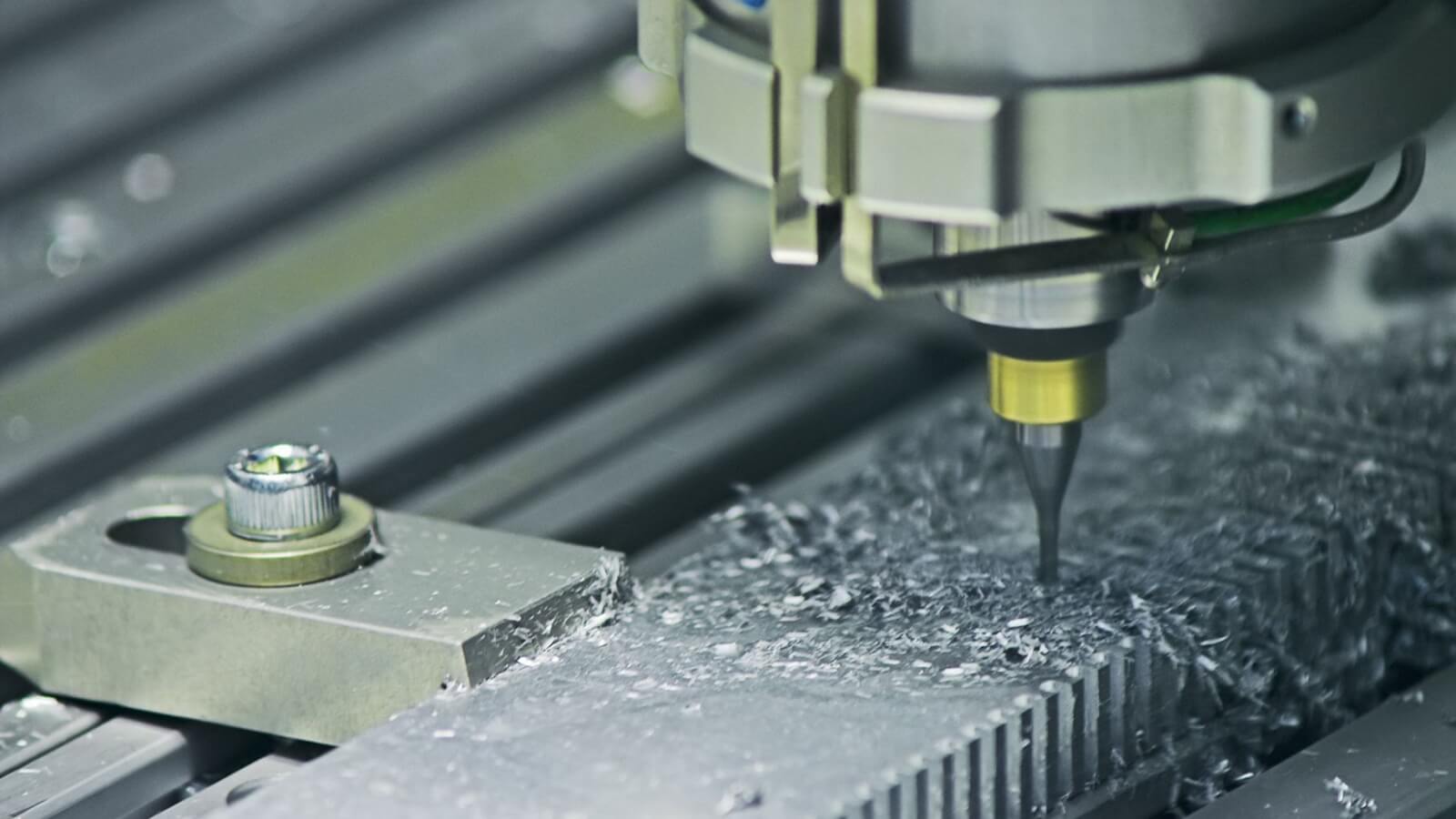
Mechanical drilling employs high-speed rotating carbide or diamond-coated bits to create through-holes and vias in rigid PCBs. This method excels in producing larger diameter holes across thicker boards, leveraging automated CNC machines for precision positioning. Drill bits plunge at thousands of revolutions per minute, removing material through shear and chip ejection, followed by desmear processes to clean resin residue. Factory operations prioritize entry and exit material control to minimize burrs and ensure uniform hole geometry. Mechanical drilling aligns well with standard production lines for consumer electronics and industrial controls, where volume justifies tooling investments. Its reliability stems from decades of refinement, making it a staple for prototypes and high-volume runs.
The process requires careful parameter tuning, such as feed rate and spindle speed, to avoid bit breakage or excessive heat buildup. Post-drilling plating fills holes to meet conductivity requirements, with inspections verifying wall roughness and plating thickness. In manufacturing environments, drill bit wear tracking is essential, as degradation affects hole quality over panels. Engineers appreciate its scalability for boards up to several millimeters thick without specialized equipment. This method supports IPC guidelines for rigid board fabrication, ensuring consistent results in controlled factory settings.
Exploring Laser Drilling Technology
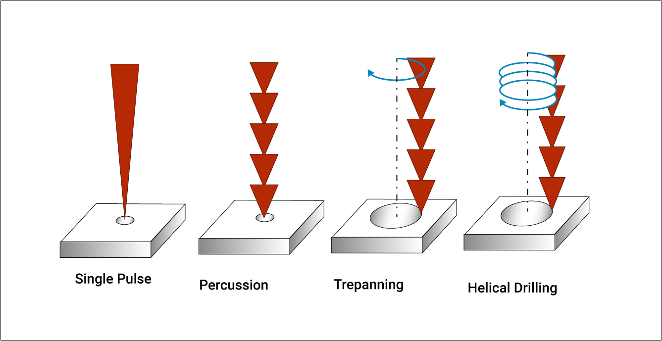
Laser drilling uses focused ultraviolet or CO2 laser beams to ablate material layer by layer, vaporizing dielectric and copper precisely. This non-contact process suits microvias, blind vias, and buried vias in high-density interconnect designs, enabling stacked or staggered configurations. Pulses deliver energy in nanoseconds, creating conical or cylindrical holes depending on wavelength and optics. Factories integrate laser stations post-lamination, often combining with plasma desmear for residue removal. The technology shines in advanced packaging for RF and computing applications, where feature sizes demand sub-100 micron precision. Unlike mechanical methods, it eliminates mechanical stress on delicate substrates.
Laser systems feature galvo scanners for rapid beam steering, boosting positional accuracy across large panels. Heat-affected zones remain minimal with UV lasers, preserving laminate integrity around vias. Production workflows include test coupon drilling to calibrate ablation rates per material stackup. This method facilitates any-layer interconnects, vital for shrinking form factors in mobile devices. Factory-driven adoption grows with HDI demands, though throughput depends on via density and panel size.
Comparing Hole Quality: Laser vs. Mechanical Drilling
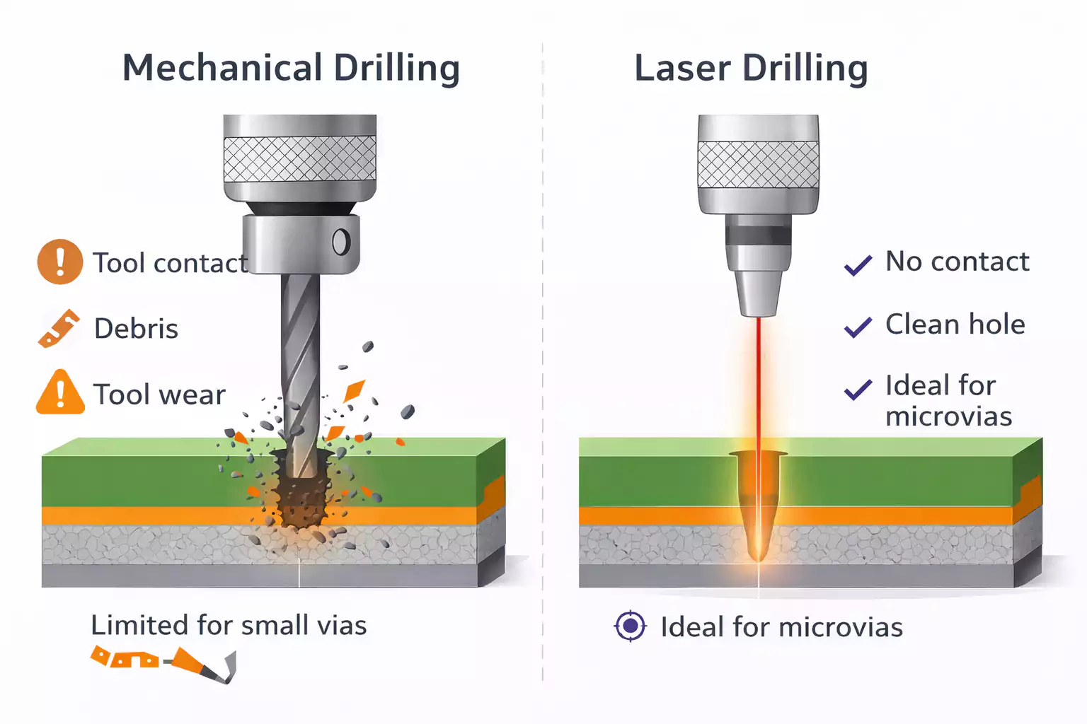
Hole quality defines plating adhesion, signal propagation, and long-term reliability, with criteria spanning wall roughness, taper, and cleanliness. Mechanical drilling often produces straighter walls for through-holes but risks smear, burrs, and drill wander, necessitating robust desmear like permanganate etching. Laser drilling yields cleaner entrances with tapered exits due to ablation dynamics, reducing debris but potentially introducing carbon residue or heat-altered resin. Cross-sections reveal mechanical holes with more uniform diameter, while laser excels in aspect ratios for shallow depths. IPC-A-600 provides acceptability criteria for these features, guiding visual and microscopic inspections in factories. Both methods require plating to achieve void-free barrels, but laser's precision minimizes breakout risks.
In high-reliability applications, mechanical drilling's robustness suits thicker boards, where laser taper might limit plating uniformity. Factories conduct pull tests and cross-section analysis to validate quality per performance specs. Laser holes often exhibit smoother dielectric interfaces post-desmear, aiding electroless copper strike. Mechanical processes benefit from peck drilling cycles to evacuate chips, enhancing wall integrity. Overall, hole quality favors laser for microvias and mechanical for standard vias, balancing project tolerances.
Production Speed and Throughput: Laser Drilling vs. Mechanical Drilling
Production speed hinges on hole count, size, and panel complexity, with mechanical drilling dominating high-volume through-hole runs. CNC drills process multiple hits per second per station, scaling via multi-spindle heads for thousands of holes per hour. Laser systems, while slower per hole due to sequential ablation, parallelize via galvo scanning for dense arrays. Factories benchmark throughput against cycle times, where mechanical suits low-density, thick boards, and laser handles HDI stacks efficiently. Tool changeovers slow mechanical lines, but bit life supports continuous runs. Laser avoids tooling but demands precise focus calibration per layer.
For prototypes, mechanical offers quicker setup, while laser accelerates microvia patterning in small batches. Panel utilization affects overall speed, as laser's non-contact nature reduces fixturing time. Manufacturing data shows mechanical excelling at 0.2mm plus holes, laser at finer pitches. Hybrid lines combine both for optimized flow. Engineers factor in desmear and plating queues, which amplify differences in full-process timelines.
Cost Analysis: Key Factors in Laser vs. Mechanical Drilling
Cost analysis reveals mechanical drilling's edge in capital and per-panel expenses for standard PCBs, with lower equipment amortization over high volumes. Drill bits represent consumables, but bulk procurement keeps costs predictable. Laser installations carry premium pricing for photonics and software, yet eliminate bit wear for microvia-heavy designs. Factory economics weigh setup, yield, and rework, where mechanical minimizes scrap on thick boards. Production speed influences labor and floor time, tilting scales per project scale. Long-term, laser's precision cuts assembly costs via better routing density.
Volume thresholds shift economics: mechanical for thousands of panels, laser for specialized runs. Material waste from drill entry pads adds minor costs, offset by faster plating readiness. Engineers model total cost of ownership, including maintenance and training. Desmear chemicals scale similarly, but laser's cleaner holes reduce etchant use. Ultimately, cost analysis favors mechanical for commodity boards, laser for performance-driven HDI.
Handling PCB Thickness in Drilling Choices
PCB thickness governs aspect ratio feasibility, with mechanical drilling tolerating higher ratios up to design limits per IPC-2221 guidelines. Thicker laminates demand robust bits to prevent deflection, ensuring centered holes across cores and prepregs. Laser drilling thrives on thinner stacks for microvias, where beam penetration controls depth accurately. Factories segment processes by thickness, using mechanical for full builds over 1.6mm and laser for buildup layers. Stacked via reliability improves with laser's control, avoiding mechanical breakout in multilayers. Thickness variations from suppliers necessitate stackup verification pre-drilling.
For rigid boards exceeding standard thicknesses, mechanical's power handles copper-heavy designs without excessive cycles. Laser risks incomplete ablation in deep holes, prompting sequential lamination. Manufacturing best practices include pilot holes for very thick panels. Engineers simulate thermal expansion to predict thickness impacts on hole registration. Choosing based on PCB thickness optimizes yield and aligns with qualification specs like IPC-6012.
Best Practices for Selecting and Implementing Drilling Methods
Evaluate project specs first: via types, densities, and tolerances dictate laser or mechanical primacy. Collaborate with fabricators early on drill charts and stackups to align capabilities. For hybrids, sequence mechanical through-holes before laser microvias to streamline flow. Implement in-line metrology for hole location and diameter, catching deviations promptly. Factory protocols emphasize cleanroom handling for laser to prevent dust-induced defects. Simulate production runs via test panels to forecast speed and cost.
Optimize parameters: spindle speeds for mechanical, pulse energy for laser, validated against material datasheets. Post-drill inspections per IPC criteria ensure compliance before plating. Yield tracking refines choices over campaigns. Procurement teams request DFM feedback incorporating drilling impacts. Sustainable practices favor laser's tool-less operation for reduced waste.
Conclusion
Laser drilling vs. mechanical drilling hinges on balancing hole quality, production speed, cost analysis, and PCB thickness demands. Mechanical methods deliver cost-effective throughput for standard through-holes in thicker boards, while laser enables precision microvias for advanced HDI. Factory insights emphasize project-specific selection to maximize yield and performance. Adhering to standards like IPC-A-600 and IPC-6012 ensures reliability across applications. Engineers benefit from hybrid approaches in complex designs, optimizing overall manufacturing efficiency. Ultimately, the better choice aligns drilling with end-product requirements for superior outcomes.
FAQs
Q1: What are the main differences in hole quality between laser drilling vs. mechanical drilling?
A1: Mechanical drilling provides straight-walled through-holes but may introduce smear requiring desmear, while laser drilling offers precise microvias with tapered profiles and minimal debris. IPC-A-600 criteria assess wall roughness and plating uniformity for both. Factories prioritize cross-section analysis to verify quality, favoring mechanical for larger holes and laser for high-density features. This impacts signal integrity in multilayer boards.
Q2: How does production speed compare in laser drilling vs. mechanical drilling for PCBs?
A2: Mechanical drilling achieves higher throughput for bulk through-holes via multi-spindle machines, processing panels rapidly. Laser drilling suits dense microvia arrays with scanning optics but slows on volume. Factory lines hybridize for balance, with speed tied to hole count and size. Engineers model cycles to meet deadlines without compromising precision.
Q3: What factors enter a cost analysis of laser drilling vs. mechanical drilling?
A3: Mechanical drilling lowers upfront costs with affordable tooling for standard runs, while laser demands higher equipment investment offset by no consumables in microvia production. Yield and rework influence totals, with mechanical excelling in high-volume thick PCBs. Factories calculate per-panel economics, recommending mechanical for prototypes and laser for HDI specialization.
Q4: When does PCB thickness favor one drilling method over the other?
A4: Thicker PCBs lean toward mechanical drilling for reliable aspect ratios per IPC-2221, handling deep through-holes effectively. Laser drilling performs best on thinner stacks for controlled microvia depths. Manufacturing adjusts stackups accordingly, ensuring plating success across thicknesses.
References
IPC-A-600K — Acceptability of Printed Boards. IPC, 2020
IPC-6012E — Qualification and Performance Specification for Rigid Printed Boards. IPC, 2017
IPC-2221B — Generic Standard on Printed Board Design. IPC, 2012


