What Are Mouse Bites in PCB Design and Manufacturing?
For those aiming to optimize their printed circuit board (PCB) manufacturing process, a thorough understanding of "mouse bites" is crucial for efficient panelization and subsequent depaneling. Mouse bites are small, perforated breakaway tabs specifically used in PCB panelization. Their purpose is to temporarily hold individual boards within a larger manufacturing panel, facilitating easier and more cost-effective separation once production and assembly are complete. This guide will explore the intricacies of PCB mouse bite design rules, including optimal hole size, spacing, panelization techniques, and a comparative analysis with V-scoring. Whether you are an experienced engineer or a hobbyist, this information will provide practical insights to enhance your PCB production workflow.
Mouse bites represent a widely adopted technique in PCB manufacturing, designed to simplify the separation of individual boards from a larger panel. A panel itself is a single sheet containing multiple identical or dissimilar PCB designs, fabricated this way to reduce costs and boost production efficiency. Mouse bites are formed by drilling a series of small holes along the connecting edges between boards, creating a perforated line. These perforations weaken the material, allowing the boards to be easily snapped apart manually or with minimal force after the assembly process. This method is particularly beneficial for irregularly shaped boards or designs that are not conducive to other depaneling techniques, helping manufacturers minimize waste, lower PCB cost, and achieve clean separations without damaging the individual PCBs.
Why Should You Use Mouse Bites for PCB Panelization?
Mouse bites offer several distinct advantages in PCB manufacturing, especially for small to medium production volumes or prototype designs. These key benefits highlight why this technique is often preferred.
Advantages of Employing Mouse Bites
● Cost-Effectiveness: Mouse bites eliminate the necessity for expensive dedicated depaneling tools or additional routing steps, leading to significant cost savings during production.
● Design Flexibility: They are highly effective for non-rectangular or complex board shapes that cannot be easily separated using straight-line cuts or V-grooves.
● Reduced Mechanical Stress: The perforated design inherently reduces mechanical stress on the PCB during separation, minimizing the risk of damage to sensitive components or traces situated near the board edges.
● Simplified Depaneling: Mouse bites enable manual separation without requiring specialized equipment, making them ideal for rapid PCB prototype manufacturing or low-volume production runs.
By strategically integrating mouse bites into your panelization strategy, you can achieve an optimal balance between manufacturing efficiency and the quality of your final PCB products.
Essential Design Rules for PCB Mouse Bites
Designing mouse bites for your PCB panel requires meticulous attention to detail to ensure clean separation and prevent potential damage to the boards. Adhering to these essential design guidelines is crucial when implementing mouse bites in your panelization process.
Optimal Hole Size for Mouse Bites
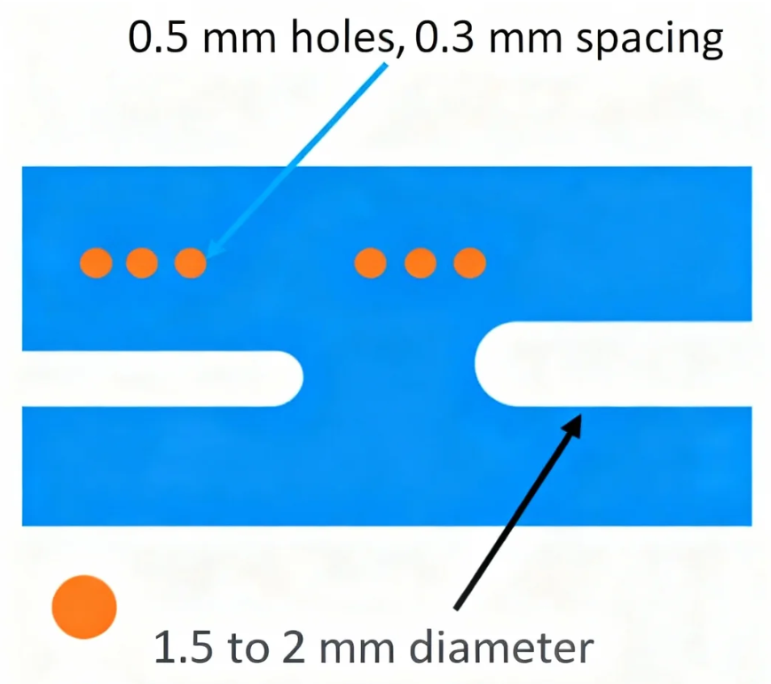
The diameter of the holes within mouse bites is critical for balancing panel integrity during manufacturing with ease of separation afterward. A common hole diameter ranges between 0.5 mm and 1.0 mm. Smaller holes (e.g., around 0.5 mm) create a stronger connection but might require more force to break apart. Conversely, larger holes (e.g., around 1.0 mm) facilitate easier separation but could potentially weaken the panel too much during handling. Many designers consider 0.8 mm as a standard starting point, as it provides a robust compromise between strength and ease of depaneling. Always consult your manufacturing partner to confirm the most suitable hole size, as board material and thickness can significantly influence structural integrity.
Appropriate Mouse Bites Spacing
The spacing between the centers of adjacent holes is another vital factor, typically ranging from 1.5 mm to 2.5 mm. A spacing of 2.0 mm is frequently recommended because it leaves sufficient material between holes to maintain panel stability throughout assembly while still allowing for a clean break. If the spacing is too tight (e.g., less than 1.5 mm), the panel might become overly fragile and break prematurely during production. Conversely, if the spacing is too wide (e.g., over 2.5 mm), separating the boards can become challenging and may result in jagged edges or damage.
Number of Holes per Mouse Bite Tab
The quantity of holes within each mouse bite section should be determined by the board's size and the required connection strength. A common practice involves using 3 to 5 holes per mouse bite tab. For smaller boards, 3 holes may be adequate, whereas larger or heavier boards might necessitate 5 holes to ensure sufficient stability during handling and assembly processes.
Strategic Placement of Mouse Bites
Mouse bites must be positioned strategically along the board edges to avoid interfering with components, traces, or other critical areas. Ideally, they should be placed in regions with at least 2 mm of clearance from any components or sensitive circuitry to prevent damage during separation. Additionally, ensure that mouse bites are evenly distributed along the edges to provide uniform support across the entire panel.
Best Practices for PCB Panelization with Mouse Bites
Panelization is the process of arranging multiple PCB designs onto a single sheet for manufacturing. When utilizing mouse bites for panelization, adhering to these best practices will maximize efficiency and quality.
● Optimize Board Layout: Arrange individual boards on the panel to minimize wasted space while ensuring ample room for mouse bites between each board. A typical gap of 2-3 mm between boards is usually sufficient for placing mouse bite tabs.
● Maintain Consistent Tab Width: Keep the width of the mouse bite tabs (the material remaining between the holes) consistent, generally around 0.5 mm to 1.0 mm, to ensure uniform strength and ease of separation.
● Consider Panel Dimensions: Ensure the overall panel size is compatible with your manufacturing equipment's capabilities. Standard panel sizes typically range, depending on the production setup.
● Account for Board Thickness: Thicker boards (e.g., 2.0 mm or more) may require larger holes or wider spacing to accommodate their increased material strength. Conversely, thinner boards (e.g., 0.8 mm) can often utilize smaller holes and tighter spacing.
By following these guidelines, you can create a panel design that streamlines production and minimizes the risk of errors during the depaneling process.
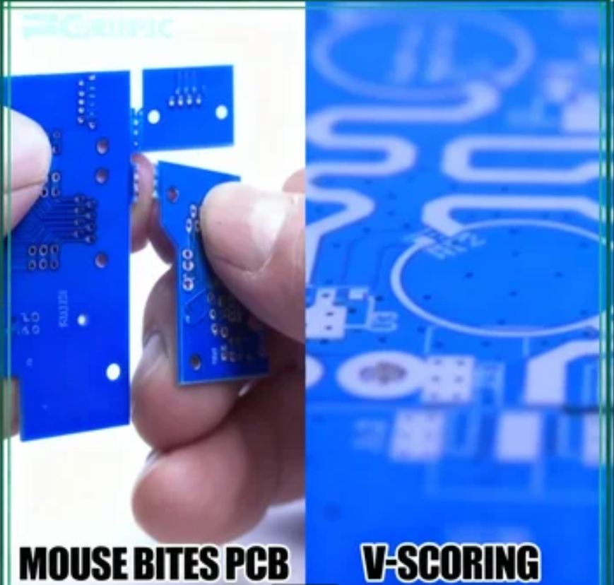
Mouse Bites vs. V-Score: Choosing the Right Depaneling Method
When considering depaneling methods, mouse bites and V-scores are two of the most prevalent techniques. Each possesses distinct strengths and weaknesses, meaning the ideal choice depends on your project's specific requirements. Let’s compare mouse bites and V-scores to help you make an informed decision.
Understanding V-Score Depaneling
A V-score is a depaneling technique where a V-shaped groove is cut into the PCB panel along the intended separation lines, typically on both the top and bottom surfaces. This groove weakens the material, allowing the boards to be cleanly snapped apart along the scored line. V-scoring is often employed for rectangular boards and in high-volume production environments.
Key Differences: Mouse Bites vs. V-Score
● Shape Compatibility: Mouse bites are highly versatile for irregularly shaped boards or designs with curved edges, as they can be strategically placed along any part of the board’s perimeter. V-scores, in contrast, are best suited for straight-line separations on rectangular boards.
● Cost Implications: Mouse bites are generally more cost-effective for small to medium production runs because they primarily utilize standard drilling tools. V-scoring can be more expensive due to the need for precise grooving equipment, particularly for larger panels.
● Edge Finish: After separation, mouse bites often leave small, rough protrusions on the board edges, which may necessitate sanding or additional finishing for aesthetic or functional reasons. V-scores typically result in cleaner, smoother edges requiring minimal post-processing.
● Component Stress: Mouse bites distribute mechanical stress more evenly during separation, thereby reducing the risk of damage to components located nearby. V-scoring can introduce more localized mechanical stress, especially if the groove is too deep or the board material is thin.
● Production Volume Suitability: Mouse bites are well-suited for prototypes or low to medium production volumes due to their simplicity and inherent flexibility. V-scores are frequently preferred for high-volume production where uniformity and speed of depaneling are critical.
When to Select Mouse Bites Over V-Score
Choose mouse bites if your project involves:
● Boards with irregular or non-rectangular shapes.
● Small to medium production runs or prototyping.
● Projects with a limited budget for depaneling processes.
● Designs where sensitive component placement near edges necessitates minimal separation stress.
Opt for V-scores if your project entails:
● Large-scale production with predominantly rectangular boards.
● Projects where a pristine, professional edge finish is essential.
● Designs that prioritize high speed and uniformity in the depaneling process.
Addressing Common Challenges with Mouse Bites
While mouse bites offer a flexible and cost-effective solution, some potential challenges can arise. Proactive measures during the design and manufacturing stages can help mitigate these issues.
Mitigating Common Issues
● Rough Edges Post-Separation: The small tabs remaining after breaking boards apart via mouse bites can result in rough edges. To address this, design mouse bites with smaller tabs (e.g., around 0.5 mm) or plan for post-separation sanding if the aesthetics or function require a perfectly smooth edge.
● Premature Panel Breakage: If the panel's structural integrity is compromised by overly large holes or excessively tight spacing, it may break prematurely during handling. Utilizing a hole size of 0.8 mm and a spacing of 2.0 mm as a starting point generally ensures sufficient stability.
● Component Damage During Separation: Placing mouse bites too close to critical components increases the risk of damage during depaneling. Always maintain at least 2 mm of clearance between mouse bites and any sensitive areas of the board.
Practical Tips for Integrating Mouse Bites into Your PCB Projects
To maximize the benefits of mouse bites in your PCB panelization strategy, consider these practical tips.
Implementation Best Practices
● Early Collaboration: Engage with your manufacturing partner early in the design phase to confirm their specific requirements and recommendations for mouse bite dimensions and panelization.
● Utilize Design Software: Leverage PCB design software that facilitates the easy addition of mouse bite footprints to your panel layout, ensuring precise placement and spacing.
● Prototype Testing: Conduct a small prototype run to thoroughly test your panel design, identifying any potential issues related to mouse bite strength or separation behavior before commencing full-scale production.
● Clear Documentation: Ensure all mouse bite specifications are clearly documented within your design files to prevent miscommunication with the manufacturer.
Conclusion: Streamlining PCB Production with Mouse Bites
Mastering the application of mouse bites is an invaluable skill for any PCB designer or engineer striving to optimize panelization and depaneling processes. By diligently following the PCB mouse bite design rules outlined in this guide—including selecting appropriate hole size (e.g., 0.8 mm), spacing (e.g., 2.0 mm), and strategic placement—you can ensure efficient production and consistently high-quality results. Whether you are deliberating between mouse bites and V-scores or planning PCB panelization with mouse bites, a comprehensive understanding of these techniques will empower you to make informed decisions for your projects.
Mouse bites offer a cost-effective and flexible solution applicable to a diverse range of PCB designs, particularly beneficial for prototypes and small to medium production volumes. With careful planning and meticulous attention to detail, you can effectively minimize challenges such as rough edges or premature panel breakage, thereby ensuring a seamless manufacturing process from initial design to final product. Incorporate these best practices into your upcoming projects to save time, reduce costs, and achieve professional-grade outcomes.