Introduction
PCB gold fingers represent the gold-plated edge connectors that enable reliable electrical connections in various electronic devices. For electronic hobbyists building custom expansions, retrofitting old hardware, or prototyping add-on boards, these components are crucial for seamless integration into slots like those in motherboards or backplanes. Improper handling during insertion and extraction can lead to plating wear, poor conductivity, or complete failure, shortening the lifespan of both the PCB and the connector. Mastering proper techniques ensures durable performance and prevents costly rework. This guide focuses on practical steps tailored for hobbyists, drawing from established engineering principles to extend connector life effectively.
What Are PCB Gold Fingers and Why Do They Matter?
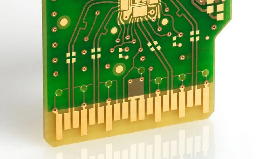
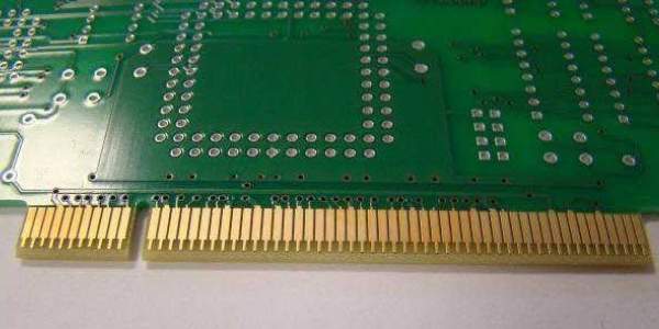
Gold fingers are precisely plated contact pads along the edge of a printed circuit board, designed for repeated mating with socket connectors. The gold plating provides excellent conductivity, corrosion resistance, and low contact resistance, making them ideal for high-reliability applications. In hobbyist projects, such as graphics card mods or ISA bus extensions, gold fingers facilitate hot-swappable connections without soldering. Their thin gold layer, typically over a nickel barrier, wears with friction from insertions, directly impacting signal integrity and power delivery. Understanding their role helps hobbyists select boards suited for frequent handling and avoid premature degradation. Adhering to guidelines like those in IPC-A-600 ensures acceptability criteria for plating quality and edge treatments are met.
The Technical Principles Behind Gold Finger Wear
Insertion and extraction involve mechanical friction between the gold fingers and the socket's spring contacts, which can scrape away the soft gold layer over time. Beveling the PCB edge at an angle, often around 45 degrees, guides the fingers into alignment and distributes initial contact forces evenly. Without this, misalignment causes scraping and uneven wear, accelerating plating loss. Extraction applies reverse shear forces, potentially bending fingers or delaminating the plating if pulled at an angle. Factors like contamination, oxidation, or excessive force amplify damage, leading to intermittent connections or arcing. Proper design principles minimize these stresses, aligning with performance specs in IPC-6012 for rigid printed boards.
Proper PCB Insertion Techniques
Start by visually inspecting both the gold fingers and the socket for debris or bent pins to ensure clean mating. Align the PCB perpendicular to the slot, using the bevel as a guide to seat the leading fingers gently without forcing. Apply even, downward pressure across the board's trailing edge using both hands or a broad pusher tool, avoiding leverage from one corner that could warp the PCB. Insert slowly to allow spring contacts to engage progressively, reducing peak friction. Once seated, verify full engagement by checking for flush alignment and secure latch if present. These steps embody proper PCB insertion techniques, preventing scratches and preserving plating for hundreds of cycles.
Preventing Damage to Gold Fingers During Handling
Handle PCBs by their edges only, wearing an ESD wrist strap to avoid static discharge that could pit the gold surface. Store boards in anti-static bags or foam inserts to prevent abrasion from stacking. Limit insertion cycles based on expected use, as each mate-or unmate cycle erodes the gold incrementally. During prototyping, use alignment fixtures or 3D-printed guides to maintain parallelism. If fingers show signs of dulling, halt use to avoid compounding damage from poor contact pressure. Following IPC-1601 guidelines for PCB handling and storage further safeguards against environmental factors like humidity that promote corrosion.
Safe Extraction Methods and Tools for PCBs
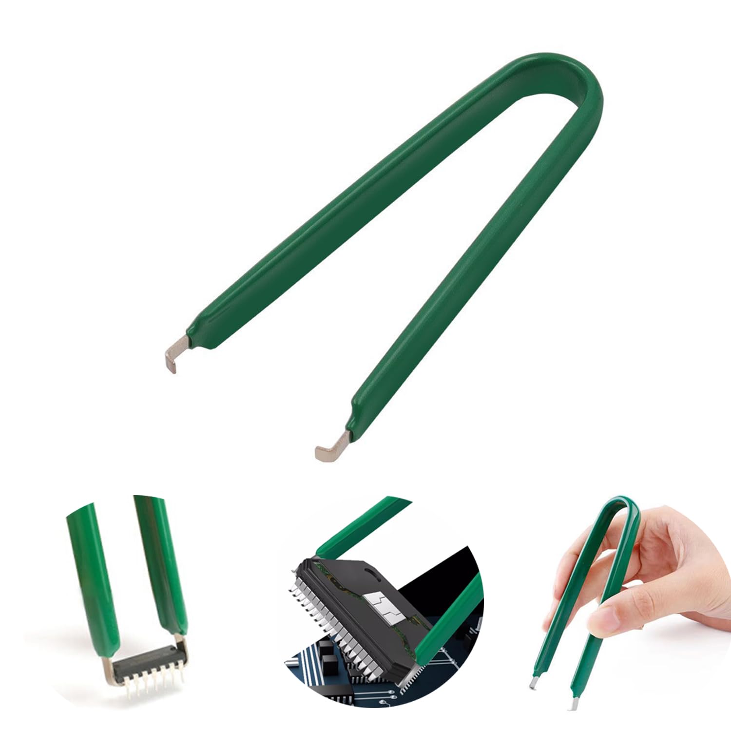
For extraction, release any latches first and grip the PCB edges firmly with ESD-safe gloves or tools. Pull straight upward with steady, even force, rocking slightly if needed but never twisting to avoid shearing contacts. Hobbyists can employ simple extraction tools for PCBs, such as plastic card pullers or broad anti-static handles that distribute force across the board. Avoid metal tools that could short circuits or scratch plating. If the board resists, check for bent socket pins rather than forcing it. This methodical approach minimizes lateral friction and preserves finger integrity for future use.
Cleaning Gold Fingers for Better Contact
Routine cleaning maintains low resistance and reliable mating. Use a soft, static-free eraser or microfiber cloth lightly rubbed along the fingers to remove oxidation or residue, following the grain to avoid abrasion. For stubborn contaminants, apply isopropyl alcohol sparingly with a cotton swab, then wipe dry immediately to prevent moisture wicking. Avoid harsh chemicals or ultrasonic baths that could delaminate plating. After cleaning, inspect under magnification for uniformity and test continuity if possible. Cleaning gold fingers for better contact is a quick hobbyist ritual that restores performance without specialized equipment.
Reducing Friction on Gold Fingers
Incorporate beveling during PCB design to ramp the socket engagement gradually, slashing initial insertion force. Lightly apply a contact lubricant rated for electronics on the fingers before mating, ensuring it evaporates without residue to cut friction coefficients. Select sockets with smooth beryllium-copper springs for compliant pressure without gouging. During frequent testing, space insertions to allow heat dissipation, as elevated temperatures soften gold further. These measures, combined with precise alignment, extend operational life significantly. Hobbyists benefit from prototyping with friction-reducing features to simulate production reliability.
Troubleshooting Common Insertion and Extraction Issues
If insertion feels gritty, clean both surfaces and check for debris in the socket. Sticking during extraction often signals bent fingers or swollen contacts from humidity; gently realign with plastic tweezers. Intermittent connectivity post-mating points to plating wear or misalignment; measure resistance across pins. Warped boards exacerbate uneven pressure, so verify flatness on a surface plate. For hobby projects, logging cycle counts helps predict failure. Addressing these promptly prevents cascading failures in multi-board setups.
Conclusion
Mastering PCB gold finger insertion and extraction hinges on alignment, gentle force, cleaning, and friction reduction. Beveling, proper tools, and handling per standards like IPC-1601 prolong connector life, saving time and resources for hobbyists. Implement these techniques in your next project to achieve robust, repeatable connections. Consistent application yields reliable electronics that stand up to repeated use.
FAQs
Q1: What are the best proper PCB insertion techniques for gold fingers?
A1: Align the beveled edge perpendicular to the socket and apply even pressure across the board. Use both hands or a pusher for balance, inserting slowly to let contacts engage progressively. Inspect beforehand to prevent damage to gold fingers. This method ensures smooth mating and longevity.
Q2: How can I prevent damage to gold fingers during frequent extractions?
A2: Pull straight with ESD-safe grips, avoiding twists or prying. Limit cycles and use plastic extraction tools for PCBs to distribute force. Clean regularly to maintain low friction. Store in protective packaging per handling guidelines. These steps preserve plating integrity.
Q3: What tools work well as extraction tools for PCBs?
A3: Plastic card pullers or broad anti-static handles provide safe leverage without scratching. ESD gloves enhance grip and protection. Avoid metal for short risk. Pair with alignment checks for damage-free removal. Simple tools suffice for hobby use.
Q4: Why is cleaning gold fingers for better contact important?
A4: Residue raises resistance, causing signal loss or heat. Soft erasers or alcohol wipes restore conductivity affordably. Reduces friction on gold fingers for easier insertions. Perform before each mate in prototypes. Keeps connections reliable long-term.
References
IPC-A-600K — Acceptability of Printed Boards. IPC, 2020
IPC-6012E — Qualification and Performance Specification for Rigid Printed Boards. IPC, 2017
IPC-1601A — Printed Board Handling and Storage Guidelines. IPC, 2008


