Why Tailoring Laser Drilling Parameters is Essential for PCB Materials
For engineers and manufacturers aiming to produce high-quality printed circuit boards (PCBs), optimizing laser drilling parameters for materials such as FR-4, Rogers laminates, ceramics, PTFE, or metal core PCBs is critically important. Laser drilling offers a highly precise and efficient method for creating vias and holes in these boards. However, to achieve optimal results with minimal damage or defects, the laser settings must be carefully adapted to the unique characteristics of each material. This guide will explore the specific laser drilling parameters required for various PCB materials, offering actionable insights to enhance your PCB production process.
The Role of Laser Drilling in Modern PCB Manufacturing
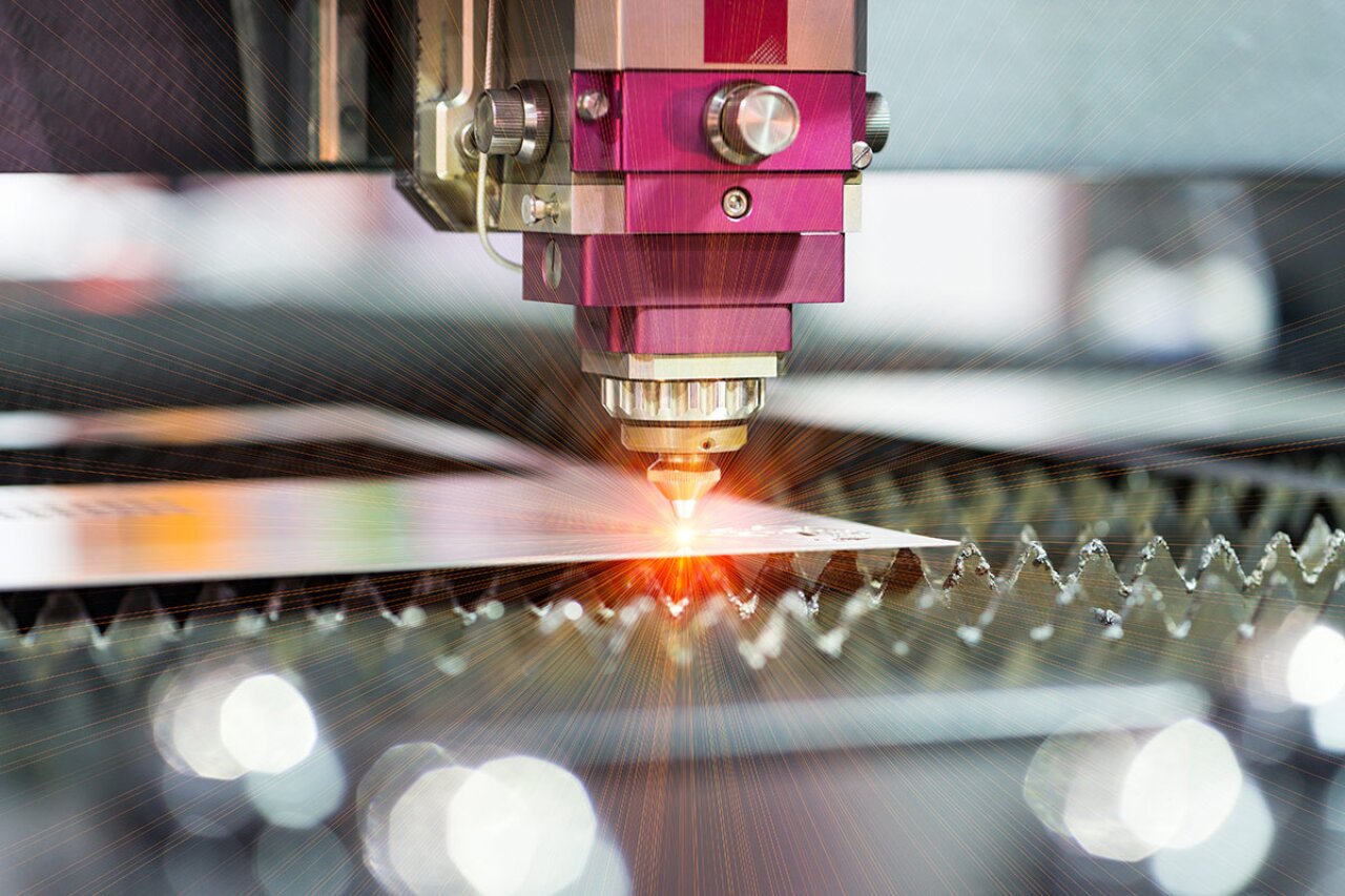
Laser drilling has become a cornerstone of contemporary PCB manufacturing due to its capacity to produce small, highly accurate holes (vias). In contrast to conventional mechanical drilling, laser drilling employs a focused light beam to remove material, making it ideal for high-density interconnects and microvias. Nevertheless, different PCB materials possess distinct properties—such as varying thermal conductivity, dielectric constants, and hardness—which necessitate specific laser settings. Failing to adjust these settings can lead to issues like charring, cracking, or substandard hole quality.
This guide will delve into the nuances of fine-tuning laser drilling parameters for commonly used PCB materials, including FR-4, Rogers, ceramic, PTFE, and metal core PCBs. By understanding each material’s characteristics and adjusting settings such as laser power, pulse duration, and repetition rate, you can achieve superior outcomes in your manufacturing process.
Understanding the Impact of Laser Drilling Parameters
Before delving into specific materials, it's crucial to grasp why laser drilling parameters are so significant. Settings like laser wavelength, power, pulse duration, and focus spot size directly influence the quality of the drilled holes. Incorrect parameter choices can result in a range of problems:
● Excessive thermal damage or burning of the material.
● Incomplete material removal, leading to poor via conductivity.
● Cracking or delamination in brittle or multi-layer materials.
● Inconsistent hole sizes, compromising the reliability of the PCB.
Optimizing these parameters ensures the creation of clean, precise holes, reduces manufacturing defects, and ultimately enhances the overall performance of the multilayer PCB. Let's now examine the best practices for each material type.
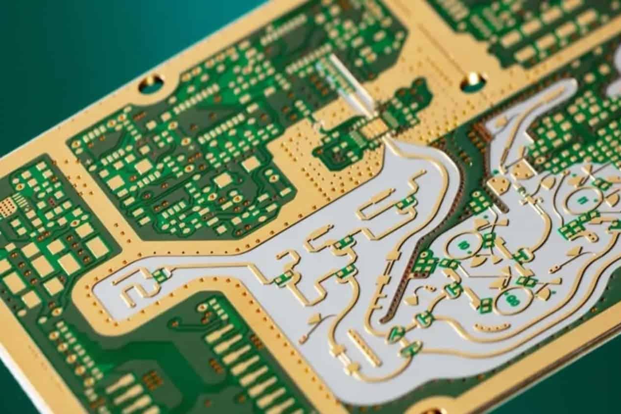
Laser Drilling Guidelines for FR-4 Material
FR-4 is among the most widely used PCB materials, composed of woven fiberglass cloth bonded with an epoxy resin. While it's cost-effective and prevalent in consumer electronics, its composite nature makes laser drilling challenging due to the differing thermal responses of glass and resin.
Optimal Parameters for FR-4
● Laser Type: CO2 lasers (with a wavelength around 10.6 μm) are frequently chosen for FR-4 because they efficiently ablate the epoxy resin. UV lasers (355 nm) are also suitable for creating finer vias.
● Power: Moderate power levels (typically 10-20 W for CO2 lasers) are recommended to prevent excessive heat buildup, which can cause charring of the resin.
● Pulse Duration: Short pulses (ranging from microseconds to nanoseconds) are crucial for minimizing thermal damage to the surrounding material.
● Repetition Rate: A rate between 20-50 kHz provides a good balance between drilling speed and precision, helping to avoid overheating.
● Focus Spot Size: A smaller spot size (20-50 μm) is ideal for microvias, ensuring clean, well-defined edges.
Expert Tip: For larger holes in PCB FR-4, employing a trepanning method (a circular laser movement) can reduce hole taper and improve wall quality. Additionally, ensuring efficient debris removal during drilling is vital to prevent residue accumulation, which can negatively impact conductivity.
Laser Drilling Guidelines for Rogers Materials
Rogers materials are high-frequency laminates commonly utilized in RF and microwave applications, valued for their low dielectric loss and stable electrical properties. These materials, which include hydrocarbon-based and PTFE-based composites, demand careful handling during laser drilling to preserve their performance characteristics.
Optimal Parameters for Rogers
● Laser Type: UV lasers (355 nm) are preferred for Rogers materials, delivering cleaner cuts with minimal thermal impact.
● Power: Low to moderate power (5-15 W) is critical to prevent damage to the delicate dielectric layers.
● Pulse Duration: Ultra-short pulses (nanoseconds) are essential to avoid the creation of heat-affected zones (HAZ) that could alter the material’s dielectric constant, which typically ranges from 2.2 to 3.5 for Rogers laminates.
● Repetition Rate: A higher repetition rate (50-100 kHz) contributes to smoother hole walls and faster processing times.
● Focus Spot Size: A very tight focus (15-30 μm) is necessary for the precision required in high-frequency designs.
Expert Tip: Rogers materials often feature copper cladding; therefore, precisely adjust the laser energy to avoid over-penetration or damage to the copper. Post-drilling inspection for dielectric integrity is also recommended, as even minor thermal damage can impact signal speeds (which are often around 0.7-0.8 times the speed of light in a vacuum for high-frequency designs).
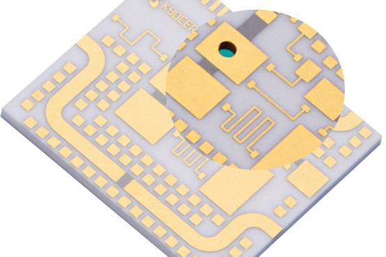
Laser Drilling Guidelines for Ceramic PCBs
Ceramic PCBs, frequently composed of materials like alumina (Al2O3) or aluminum nitride (AlN), are deployed in high-power and high-temperature applications due to their exceptional thermal conductivity (up to 170 W/m·K for AlN) and superior electrical insulation. However, their inherent hardness and brittleness make laser drilling a delicate process.
Optimal Parameters for Ceramic PCBs
● Laser Type: UV lasers (355 nm) or femtosecond lasers are best suited for ceramics, as they minimize cracking and thermal stress.
● Power: Higher power (20-30 W) may be necessary due to the material’s hardness, but it must be meticulously controlled to prevent damage.
● Pulse Duration: Ultra-short pulses (femtoseconds to picoseconds) are paramount for preventing micro-cracks in the brittle substrate.
● Repetition Rate: Lower rates (10-30 kHz) aid in managing heat dissipation within the material.
● Focus Spot Size: A small spot size (10-20 μm) ensures precision without excessive material removal.
Expert Tip: For ceramics, utilize a percussion drilling technique (repeated pulses at a single point) to gradually remove material without inducing fractures. Integrating cooling systems during the drilling process can also help to mitigate thermal stress.
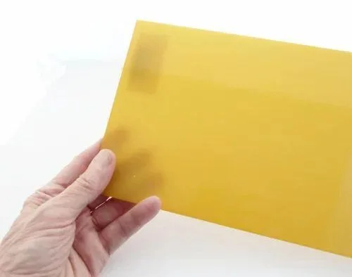
Laser Drilling Guidelines for PTFE Materials
PTFE (polytetrafluoroethylene), commonly known as Teflon, is a favored material for high-frequency and high-performance PCBs due to its exceptionally low dielectric constant (approximately 2.1) and excellent chemical resistance. However, its soft and heat-sensitive nature demands precise laser control.
Optimal Parameters for PTFE
● Laser Type: UV lasers (355 nm) are ideally suited for PTFE, enabling clean cuts without excessive melting.
● Power: Low power (5-10 W) is essential to prevent melting or deformation of this soft material.
● Pulse Duration: Short pulses (nanoseconds) minimize thermal damage to the surrounding area.
● Repetition Rate: Moderate rates (30-60 kHz) strike a balance between drilling speed and quality.
● Focus Spot Size: A small spot size (15-25 μm) ensures precision for creating microvias in high-frequency designs.
Expert Tip: Given PTFE’s typically low glass transition temperature, maintaining minimal heat input is critical. Employ a robust debris removal system to prevent molten material from redepositing on the PCB surface, which could compromise signal integrity.


