Introduction
As an electronic hobbyist, you have likely spent hours designing and fabricating your own printed circuit boards (PCBs) for fun projects like LED displays or sensor circuits. Ensuring the quality of these DIY PCBs can mean the difference between a working prototype and endless debugging sessions. Poor quality control often leads to frustrating issues such as intermittent connections or outright failures during operation. This guide focuses on simple, accessible methods tailored for beginners, helping you perform a reliable DIY PCB quality check without expensive equipment. We will cover visual PCB inspection for hobbyists, basic electrical tests, and mechanical checks, all while aligning with key industry standards. By the end, you will have the confidence to verify your boards step by step.
Why PCB Quality Control Matters for Hobbyists
Quality control in PCB fabrication ensures reliability, safety, and performance, especially when you are etching boards at home or ordering small batches. Hobby projects often operate in uncontrolled environments, like garages or workshops, where contaminants or handling errors can introduce defects. Skipping checks might result in shorts, open circuits, or mechanical weaknesses that cause failures under heat or vibration. For instance, a warped board could misalign components during soldering, leading to cold joints. Implementing simple PCB testing methods early saves time and materials in the long run. Adhering to principles from standards like IPC-A-600K helps even hobbyists achieve professional-level results without formal training.
In the broader context, consistent quality control builds skills transferable to more complex builds, such as Arduino shields or custom amplifiers. It also prevents safety hazards, like overheated traces from poor etching. Hobbyists frequently overlook these steps due to excitement over assembly, but a quick routine transforms unreliable prototypes into dependable creations. Ultimately, mastering these basics empowers you to iterate faster and enjoy your electronics hobby more fully.
Common PCB Defects and Their Causes in DIY Projects
Understanding defects is the foundation of effective quality control. Visual issues like burrs on edges or incomplete etching often stem from improper exposure in photoresist processes or uneven etchant application. Mechanical problems, such as bow and twist, arise from uneven copper distribution or cooling stresses during fabrication. Electrical faults, including opens or shorts, result from over-etching traces or drill misalignment. Contamination from fingerprints or residues can degrade solderability over time. Recognizing these patterns allows hobbyists to spot issues early through visual PCB inspection for hobbyists.
Factory-driven insights reveal that most defects in small-scale production trace back to process variations, a common pitfall in home setups. For example, insufficient rinsing after etching leaves copper salts that promote corrosion. Dimensional inaccuracies, like oversized holes, often occur due to drill bit wear or improper fixturing. By categorizing defects as cosmetic, functional, or reliability-related, you prioritize checks accordingly. Standards like IPC-6012E outline acceptable limits for these, providing a benchmark even for non-commercial boards. Awareness of causes guides preventive measures in your workflow.
Visual PCB Inspection for Hobbyists: Step-by-Step Guide
Start your DIY PCB quality check with a thorough visual examination using a magnifying glass or loupe at 10x to 20x magnification. Inspect the outer layers first for uniform copper traces, checking for nicks, scratches, or mouse bites along edges. Verify that pads are free of lifts or cracks, and ensure no bridging between adjacent traces. Examine vias and holes for clean barrels without burrs protruding into the interior. Look for discoloration or haze on the solder mask, which might indicate contamination. This simple PCB testing method catches over 70 percent of issues before assembly.
Next, flip the board to check the backside, paying attention to silkscreen legibility and alignment. Run your finger lightly over surfaces to feel for raised particles or roughness. Hold the board at an angle under bright light to reveal subtle shadows from warpage or delamination. Compare against IPC-A-600K criteria for Class 2 boards, which tolerate minor imperfections suitable for hobby use. Document findings with photos for reference in future projects. Consistent visual PCB inspection for hobbyists builds intuition for quality over time.
Under natural or LED lighting, scan for foreign materials like fibers or dust trapped in crevices. Pay special attention to plated through-holes, ensuring shiny, uniform plating without voids. If using FR-4 material, check for fiberglass weave exposure from mask scratches. This inspection typically takes 10 to 15 minutes per board but prevents costly rework. Integrate it as the first step in your routine for reliable results.
Simple Mechanical and Dimensional Checks
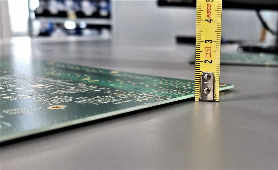
Beyond visuals, measure board dimensions with a digital caliper for length, width, and thickness tolerances, aiming for plus or minus 0.1 mm accuracy on critical features. Check hole sizes and spacing against your design files to confirm drill accuracy. Assess warpage by placing the board on a flat surface and using a straightedge or feeler gauge; acceptable bow and twist should not exceed 0.75 percent of board dimensions per IPC standards.
Test for cleanliness by wiping surfaces with isopropyl alcohol on a lint-free cloth; residues should not streak or leave haze. Bake the board at low temperature, around 100 degrees Celsius for one hour, to check for outgassing or delamination, a simple reliability test. Inspect edge quality for chamfers or roughness that could snag wires. These mechanical checks ensure mechanical integrity for soldering and mounting.
Electrical Testing: Basic Continuity and Insulation Checks
With a multimeter set to continuity or resistance mode, probe between traces to detect opens or shorts. Verify continuity along each net by touching probes to pads or test points, expecting low resistance under 10 ohms for short paths. Check for shorts by probing adjacent nets, where infinite resistance confirms isolation. This core simple PCB testing method uncovers fabrication flaws like bridged vias.
For insulation integrity, measure resistance between power and ground planes at over one megaohm. Test after visual inspection to avoid false positives from debris. Use a powered-up test jig if available, lighting up nets sequentially to visualize breaks. These steps align with functional verification principles in J-STD-001, adapted for hobby tools. Perform tests in a static-free environment to prevent ESD damage.
Sweep probes systematically across the board, logging any anomalies. Repeat after flexing the board slightly to detect hidden cracks. This methodical approach catches intermittent issues early.
Best Practices for Preventing Defects in Home Fabrication
Adopt a clean workspace with dedicated tools to minimize contamination during etching and drilling. Use fresh etchant and agitate uniformly for consistent copper removal. Fixture boards securely during machining to avoid movement-induced errors. After processing, rinse thoroughly and dry completely before inspection. Store boards in anti-static bags to preserve quality.
Incorporate design reviews pre-fabrication, ensuring trace widths meet current needs and clearances prevent shorts. Prototype on small panels to test processes before full runs. Follow drying cycles post-wet processes to avoid moisture traps. These habits, drawn from factory protocols, elevate hobbyist outcomes.
Troubleshooting Common Hobby PCB Issues
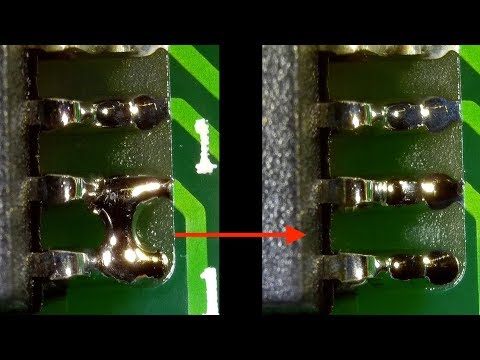
If shorts appear, revisit etching uniformity or mask adhesion. Opens often trace to over-etching; adjust exposure times. Warpage signals thermal mismatch; use symmetric copper pours. Poor solderability from oxidation requires flux cleaning. Systematic isolation with multimeter divides the board into sections for pinpointing faults. Patience here refines your skills.
Conclusion
Mastering PCB quality control transforms hobby projects from hit-or-miss to consistently successful. Start with visual PCB inspection for hobbyists, progress to electrical and mechanical simple PCB testing methods, and integrate best practices for prevention. Referencing standards like IPC-A-600K and IPC-6012E provides reliable benchmarks. Regular routines save time, reduce waste, and boost confidence. Apply these DIY PCB quality check techniques to your next build and enjoy more reliable electronics.
FAQs
Q1: What are the most important steps in a DIY PCB quality check for beginners?
A1: Visual inspection tops the list, followed by continuity testing with a multimeter and dimensional measurements. Use a magnifier to spot etching defects or burrs, then verify traces for opens and shorts. Check warpage on a flat surface. These simple PCB testing methods catch most issues early, ensuring your board is assembly-ready without advanced tools.
Q2: How do I perform visual PCB inspection for hobbyists at home?
A2: Gather a bright light, 10x magnifier, and clean workspace. Examine traces for uniformity, pads for lifts, and holes for burrs. Angle the board to detect warpage or delamination. Wipe with isopropyl alcohol to test cleanliness. This foundational step aligns with IPC-A-600K acceptability criteria for reliable hobby boards.
Q3: What basic tools do I need for simple PCB testing methods?
A3: A digital multimeter for continuity and resistance, calipers for dimensions, a straightedge for warpage, and a magnifying loupe suffice. Isopropyl alcohol and lint-free cloths aid cleanliness checks. These affordable items enable comprehensive DIY PCB quality checks, from electrical verification to mechanical integrity.
Q4: Why does warpage matter in hobby PCB projects?
A4: Warpage misaligns components during soldering, causes poor connections, and stresses traces under operation. Measure with a feeler gauge against IPC-6012E limits, typically under 0.75 percent. Prevent it via balanced copper layouts and controlled cooling. Addressing this ensures stable, long-lasting boards for your circuits.
References
IPC-A-600K — Acceptability of Printed Boards. IPC, 2020
IPC-6012E — Qualification and Performance Specification for Rigid Printed Boards. IPC, 2017
J-STD-001H — Requirements for Soldered Electrical and Electronic Assemblies. IPC, 2018


