Introduction
Printed Circuit Boards, often referred to as PCBs, are the backbone of electronic devices, connecting components to ensure seamless functionality. For electronic hobbyists, encountering PCB issues such as circuit damage or faulty components is a common challenge during projects or repairs. Understanding how to diagnose and fix these problems not only saves time but also enhances skills in electronics.
This article explores frequent PCB issues, including physical damage and component failures, and provides practical steps to resolve them. Whether you are troubleshooting a malfunctioning circuit or repairing a broken trace, this guide offers clear solutions tailored for hobbyists. By mastering these techniques, you can extend the life of your projects and tackle complex repairs with confidence.
What Is PCB Repair and Why It Matters
PCB repair involves identifying and fixing faults in a printed circuit board to restore its functionality. These boards host critical components like resistors, capacitors, and integrated circuits, forming the electrical pathways necessary for device operation. When a PCB fails due to circuit damage or component issues, the entire device can malfunction, making repair skills essential for hobbyists.
The importance of PCB repair lies in cost efficiency and sustainability. Replacing an entire board can be expensive, especially for custom or vintage electronics. Repairing instead of discarding also reduces electronic waste, aligning with environmentally conscious practices. For hobbyists, learning to address common issues builds technical expertise and problem-solving abilities, enabling more ambitious projects. A damaged circuit or failed component does not have to end a project if you know the right techniques to apply.
Common PCB Issues Faced by Hobbyists
Understanding the typical problems that affect types of PCBs is the first step to effective repair. Hobbyists often encounter a range of issues stemming from physical damage, environmental factors, or component wear. Below are the most frequent challenges in PCB functionality.
Physical Damage to the Board
Physical damage often occurs during handling or assembly. Dropping a PCB or applying excessive force while soldering can crack the board or break traces. These thin copper pathways are vital for circuit connectivity, and any interruption can halt functionality. Scratches or dents may also expose underlying layers, leading to short circuits or corrosion over time.
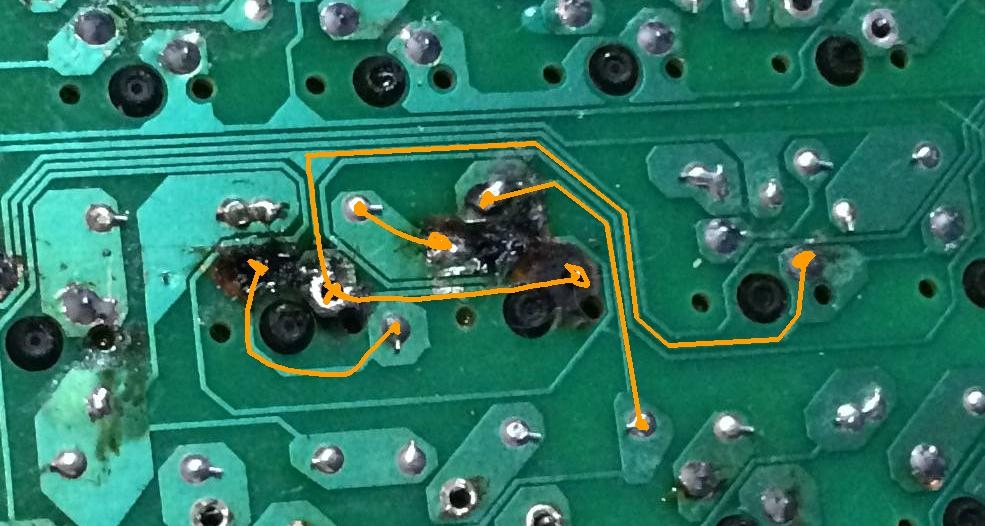
Burnt or Damaged Traces
Burnt traces result from excessive current flow or overheating during soldering. This damage disrupts the circuit, preventing signals from reaching components. Hobbyists might notice blackened areas on the board, indicating where the copper has been compromised. Identifying and repairing these traces is crucial to restoring the PCB’s operation.
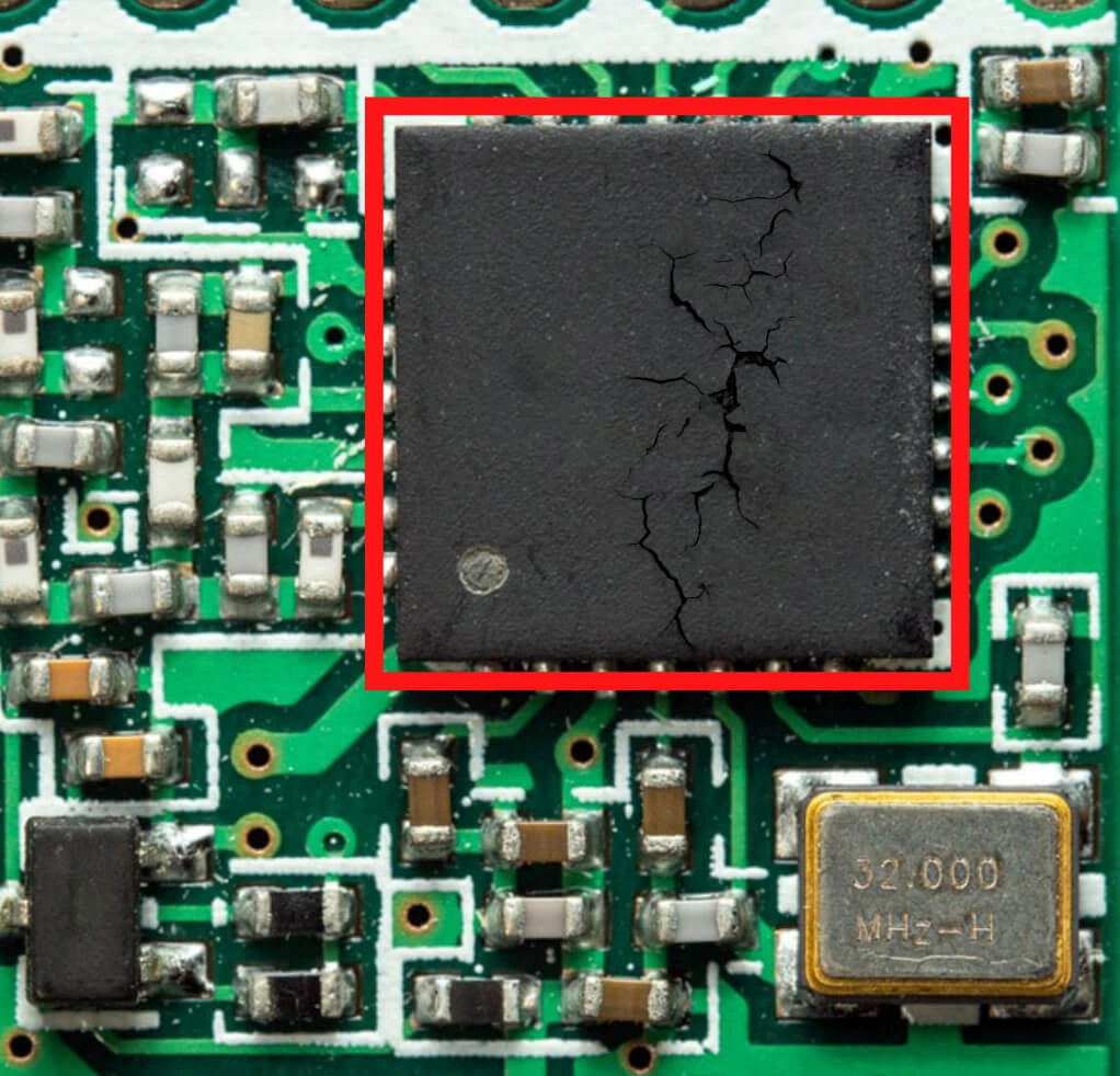
Component Failure
Components like capacitors, resistors, and diodes can fail due to age, overheating, or incorrect voltage application. A failed component often causes the entire circuit to malfunction. For instance, electrolytic capacitors are prone to leaking or bulging over time, a common issue noted in various technical discussions on social platforms. Recognizing these signs early can prevent further damage.
Soldering Issues
Poor soldering techniques often lead to cold joints or lifted pads. Cold joints occur when solder does not properly bond with the component lead, resulting in unreliable connections. Lifted pads, where the copper pad detaches from the board, can happen due to excessive heat or mechanical stress. Both issues disrupt circuit integrity and require careful repair.
Environmental Damage
Moisture, dust, and temperature extremes can degrade a PCB. Corrosion from humidity affects solder joints and traces, while dust accumulation may cause short circuits. Prolonged exposure to heat can weaken components, leading to failures. Hobbyists must store and use boards in controlled conditions to minimize these risks.
Technical Causes Behind PCB Issues
Delving into the root causes of PCB problems helps hobbyists prevent recurrence and apply targeted fixes. These causes often relate to design flaws, material limitations, or operational stress.
Overcurrent and Thermal Stress
Excessive current through a circuit generates heat, stressing both traces and components. If a design does not account for proper current ratings, traces can burn out. Thermal stress also arises during soldering if temperatures exceed the board’s tolerance, as outlined in standards like IPC-A-600K. Components may degrade under sustained high temperatures, leading to failure.
Mechanical Stress and Vibration
Mechanical stress from bending or vibration can crack a PCB or dislodge components. This is common in portable devices or projects subject to frequent movement. Even minor flexing can fracture solder joints or traces over time, disrupting the circuit. Proper mounting and support during assembly reduce this risk.
Material Degradation
PCBs are made of materials like fiberglass and copper, which can degrade under environmental exposure. Moisture can cause delamination, where layers of the board separate, while oxidation corrodes copper traces. Component materials, such as capacitor dielectrics, also wear out, especially under voltage stress, leading to circuit issues.
Design and Assembly Errors
Incorrect component placement or inadequate trace spacing during design can lead to short circuits or interference. Assembly errors, like misaligned soldering or using incompatible parts, compound these problems. Standards such as IPC-6012E emphasize the importance of design validation to avoid such faults before production or repair.
Practical Solutions for PCB Repair
Repairing a PCB requires a systematic approach, using the right tools and techniques. Below are actionable steps to address common issues, tailored for hobbyists with basic to intermediate skills.
Step 1: Visual Inspection
Start by examining the PCB under good lighting, using a magnifying glass if needed. Look for burnt traces, cracked areas, or bulging components. Check solder joints for cracks or dull appearances, which indicate cold joints. This initial assessment helps pinpoint obvious damage before deeper testing.
Step 2: Electrical Testing
Use a multimeter to test for continuity across traces and components. Set it to resistance mode to check if traces are intact or if there is a short circuit. Measure voltage at key points to identify if components receive power. For complex issues, an oscilloscope can analyze signal behavior, though this might be advanced for some hobbyists.
Step 3: Repairing Damaged Traces
For broken or burnt traces, carefully scrape away any damaged coating to expose the copper. Use a conductive pen or thin wire to bridge the gap, securing it with solder. Apply a small amount of conformal coating afterward to protect the repair. Precision is key to avoid creating new shorts.
Step 4: Replacing Faulty Components
Identify failed components by their physical condition or test results. Desolder them using a desoldering pump or wick, then clean the area with isopropyl alcohol. Install a replacement component with matching specifications, soldering it in place according to guidelines like those in IPC J-STD-001H. Verify polarity for components like capacitors.
Step 5: Fixing Soldering Issues
For cold joints, reheat the solder with a soldering iron and add fresh solder to ensure a strong bond. If a pad is lifted, use epoxy to secure it back to the board, then reinforce with a jumper wire if needed. Avoid overheating, as it can cause further damage to the circuit.
Step 6: Preventing Future Damage
After repairs, store the PCB in a dry, dust-free environment. Use antistatic bags or mats during handling to prevent static discharge. Apply conformal coating to protect against moisture if the board will be exposed to harsh conditions. Proper storage and handling minimize recurring issues.
Suggested Reading: Multilayer PCB Repair: Challenges and Solutions for Complex Circuit Boards
Troubleshooting Tips for Hobbyists
Troubleshooting a PCB can be daunting, but a structured approach simplifies the process. Start with the simplest explanations before moving to complex diagnostics. If a device does not power on, check connections and power supply first. Look for visible damage or loose components as potential culprits.
Keep a log of symptoms and test results to narrow down causes. For intermittent issues, flex the board slightly during testing to detect mechanical faults, but do so cautiously to avoid further damage. If a specific component overheats, verify its rating against the circuit’s requirements using a datasheet.
Patience is essential. Some faults, like hidden shorts, require methodical probing with a multimeter. Isolate sections of the circuit by disconnecting components one by one to identify the problem area. This approach often reveals subtle issues that visual inspection misses.
Conclusion
PCB repair is a valuable skill for electronic hobbyists, enabling the revival of damaged circuits and extending the life of projects. By understanding common issues like trace damage, component failure, and soldering problems, you can tackle repairs with confidence. Systematic inspection, precise testing, and careful restoration of components or traces often resolve most faults. Adhering to industry standards and best practices ensures repairs are durable and safe. With the right tools and techniques, hobbyists can transform a malfunctioning board into a working masterpiece, enhancing both skills and project outcomes.
FAQs
Q1: What are the most common PCB issues for hobbyists?
A1: PCB issues often include physical damage, burnt traces, and component failures. Cracks or broken traces disrupt circuits, while components like capacitors may leak or fail due to age or heat. Poor soldering can cause cold joints, leading to unreliable connections. Visual inspection and testing with a multimeter help identify these problems early for effective repair.
Q2: How can I fix circuit damage on a PCB at home?
A2: To fix circuit damage, first locate broken traces with a visual check. Scrape off any coating, then use a conductive pen or wire to reconnect the trace. Solder the repair carefully and protect it with conformal coating. Use a multimeter to confirm continuity. This method works well for minor damage with basic tools.
Q3: What tools do I need to repair component issues on a PCB?
A3: Essential tools for repairing component issues include a soldering iron, desoldering pump, multimeter, and tweezers. A magnifying glass helps inspect small parts, while isopropyl alcohol cleans solder areas. These tools allow you to remove faulty components, test for faults, and solder replacements, ensuring precise repairs for hobbyist projects.
Q4: How can I prevent PCB damage during hobbyist projects?
A4: Prevent PCB damage by handling boards with care on antistatic mats. Store them in dry, dust-free conditions to avoid corrosion. Use proper soldering techniques to prevent overheating components or traces. Following guidelines from standards like IPC helps maintain circuit integrity during assembly and testing phases.
References
IPC-A-600K — Acceptability of Printed Boards. IPC, 2020.
IPC-6012E — Qualification and Performance Specification for Rigid Printed Boards. IPC, 2020.
IPC J-STD-001H — Requirements for Soldered Electrical and Electronic Assemblies. IPC, 2021.


