Introduction
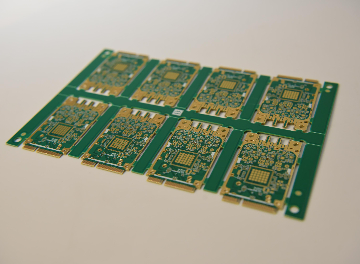
Modern PCB designs increasingly feature intricate layouts with tight spacing, fine-pitch components, and irregular outlines to meet the demands of compact electronics. Depaneling these boards from production panels requires precision to avoid damage like microcracks or component stress. Among various methods, PCB router depaneling stands out for its ability to follow complex paths cleanly. This technique uses a specialized PCB routing machine to mill separation lines, making it particularly suitable for high-density boards. Factory engineers often select it when flexibility and edge quality are priorities over sheer speed. Understanding its principles helps optimize manufacturing yields.
What Is PCB Router Depaneling and Why It Matters for Intricate Designs
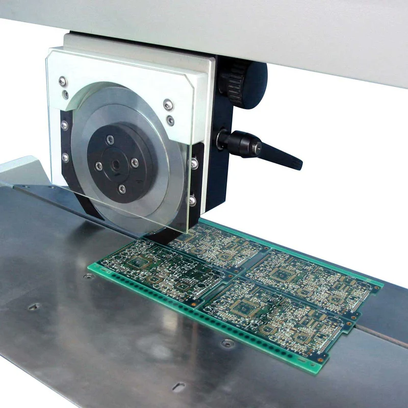
PCB router depaneling involves a CNC-controlled high-speed spindle equipped with a router bit that mills through the material connecting individual boards on a panel. The process follows pre-programmed paths to cut tabs, mouse bites, or full contours, separating boards without straight-line restrictions. Unlike V-scoring or punching, which limit shapes to linear or simple geometries, routing accommodates any outline, ideal for depaneling intricate PCBs. This matters in high-volume production where designs evolve rapidly, and panels include boards with curved edges or cutouts near sensitive areas. It minimizes mechanical stress compared to aggressive methods, preserving board integrity for downstream assembly. Factories report higher first-pass yields with routing for complex panels.
The relevance grows with shrinking component sizes and multilayer stacks, where even minor edge damage can lead to failures. Routing ensures clean separation, supporting compliance with quality benchmarks like IPC-A-600 for printed board acceptability. Engineers value its versatility in handling thicknesses from thin flex to standard rigid boards.
Technical Principles of PCB Router Depaneling
At its core, the process relies on a rotating router bit driven by a high-speed spindle, typically operating under CNC guidance to trace precise toolpaths. The bit shears through the copper-clad laminate and substrate, generating chips that must be managed to avoid rework. For intricate designs, paths offset from board edges by safe margins prevent vibration-induced defects. Spindle design incorporates air cooling to maintain consistent performance during extended runs. Material removal occurs via controlled feed rates, where the bit's geometry influences chip evacuation and heat buildup.
Dust and debris arise from milling fiberglass-reinforced materials, necessitating integrated collection to maintain cleanliness. The technique excels in flexibility, as software generates paths from Gerber or DXF files, adapting to panel variations. Edge finish depends on bit sharpness and path optimization, aligning with standards for surface quality. Vibration control through fixturing ensures straightness tolerances suitable for automated assembly.
Best Practices for Router Bit Selection in PCB Depaneling
Selecting the right router bit starts with matching flute geometry and coating to the substrate, such as carbide with diamond for abrasive FR4 composites. Spiral bits promote efficient chip removal upward, reducing recutting and heat. Diameter choice balances cut width with precision; smaller bits suit fine features but wear faster. Factory protocols recommend monitoring runout and replacing bits at signs of dulling to sustain edge quality. Testing bits on scrap panels verifies performance before production.
Integrate bit selection with panel design, placing tabs away from components with adequate clearance. Rounded tab corners distribute stress evenly. This approach supports IPC-6012 qualification for rigid printed boards by minimizing delamination risks.
Optimizing PCB Depaneling Dust Collection and Speed
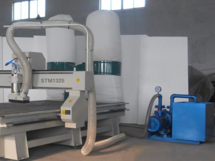
Effective dust collection uses high-volume vacuum systems integrated into the PCB routing machine enclosure, capturing particles at the source. Down-draft tables and HEPA filters prevent airborne contamination that could short circuits during assembly. Regular maintenance of filters ensures airflow, critical for cleanroom environments. Positioning nozzles close to the bit maximizes efficiency without obstructing the spindle.
PCB depaneling speed optimization involves balancing throughput with quality, slowing feeds near delicate areas to cut stress. Higher speeds boost productivity but risk burrs or microcracks; factories dial in parameters via trial runs. Automation via inline systems sequences loading, routing, and unloading, slashing cycle times for medium volumes. Programmed pauses at corners enhance precision for intricate paths.
PCB Depaneling Automation for High-Volume Intricate PCBs
Full automation in PCB router depaneling employs fiducial recognition for panel alignment, ensuring repeatability across batches. Inline machines handle continuous flow, with stackers for output organization. Vision systems detect defects mid-process, halting on anomalies. This setup scales for intricate PCBs where manual handling risks inconsistencies.
Software simulates paths pre-run, optimizing for minimal tool changes. Grounding and ESD safeguards protect boards. Such systems align with factory-driven quality controls.
Troubleshooting Common Issues in Depaneling Intricate PCBs
Vibrations often cause edge chipping; counter with rigid fixturing and balanced spindles. Inspect using magnification for microcracks post-depaneling. Dust residue leads to contamination, addressed by enhanced collection and air showers. Bit deflection in long cuts warps paths; shorten segments or use stepped depths.
Overheating dulls bits quickly, mitigated by coolant mists where compatible. Stress testing with strain gauges verifies limits before assembly. Panel warpage from prior processes amplifies issues, requiring flatness checks.
Conclusion
PCB router depaneling proves a reliable choice for intricate designs, offering unmatched flexibility and precision through CNC milling. Proper bit selection, dust collection, speed tuning, and automation elevate its effectiveness in production. Factories achieve superior edge quality and yields by integrating these practices with standards like IPC-A-600. As designs grow complex, this method supports reliable manufacturing without excessive stress. Engineers should prioritize panel design synergy for optimal results.
FAQs
Q1: What makes PCB router depaneling ideal for depaneling intricate PCBs?
A1: Router depaneling excels with complex outlines via programmable paths, unlike linear methods. It delivers clean cuts with low stress on fine features and high-density components. Factories use it for irregular shapes, ensuring edge quality per IPC standards. Automation enhances repeatability for production scales. (52 words)
Q2: How does router bit selection impact PCB depaneling performance?
A2: Bit geometry and material dictate chip removal, heat, and wear in routing. Diamond-coated spirals suit composites, maintaining sharpness longer. Select based on thickness and path length to avoid deflection. Regular inspection prevents defects, supporting consistent factory output. (48 words)
Q3: Why is PCB depaneling dust collection critical in routing processes?
A3: Dust from milling contaminates components and affects assembly yields. Integrated vacuums capture particles at source, using HEPA for cleanliness. Poor management risks shorts or rework. Essential for high-volume runs with intricate boards. (42 words)
Q4: What role does PCB depaneling automation play with routing machines?
A4: Automation aligns panels via fiducials, programs paths, and integrates inspection for hands-free operation. It cuts cycle times and errors in intricate depaneling. Ideal for medium-to-high volumes, boosting throughput while upholding quality. (45 words)
References
IPC-A-600K — Acceptability of Printed Boards. IPC, 2020
IPC-6012E — Qualification and Performance Specification for Rigid Printed Boards. IPC, 2017
IPC-2221B — Generic Standard on Printed Board Design. IPC, 2012


