Introduction
Impedance-controlled printed circuit boards form the backbone of modern high-speed electronics, where signal integrity directly impacts performance. Selecting appropriate PCB materials ensures that transmission lines maintain consistent characteristic impedance, minimizing reflections and losses. Key properties like PCB material dielectric constant and PCB loss tangent play pivotal roles in achieving this control. Engineers often compare standard options such as FR-4 with advanced high-frequency PCB materials to balance cost, performance, and manufacturability. This article provides a structured comparison, drawing on engineering principles to guide material selection for impedance-controlled designs. Understanding these factors helps in optimizing designs for applications ranging from telecommunications to automotive systems.
Understanding Impedance Control in PCBs
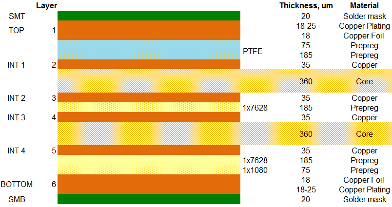
Characteristic impedance in PCBs arises from the interaction between trace geometry, conductor properties, and the surrounding dielectric. It is primarily determined by the formula Z0 equals square root of inductance over capacitance, where capacitance depends heavily on the PCB material dielectric constant. Variations in dielectric constant lead to impedance mismatches, causing signal reflections that degrade high-speed performance. Impedance control requires precise stackup design, including core thickness, prepreg layers, and copper weight, all influenced by material choices. Industry standards like IPC-2141A outline design guidelines for high-speed controlled impedance circuit boards, emphasizing the need for stable material properties. Proper control ensures signals propagate with minimal distortion, critical for data rates exceeding several gigabits per second.
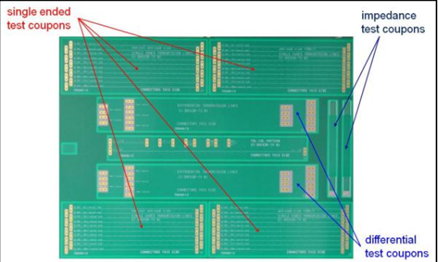
Maintaining tight impedance tolerances, typically ±10% or better, demands materials with low variability in electrical properties. Factors such as frequency dependence and temperature stability further complicate selection. Engineers must evaluate how materials perform under operating conditions to avoid issues like crosstalk or attenuation. Visual inspection of fabricated test coupons verifies compliance during manufacturing.
Key Material Properties Affecting Impedance Control
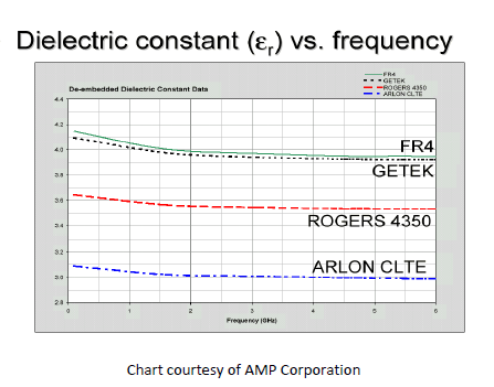
The PCB material dielectric constant, or relative permittivity (Dk), defines how much a material concentrates electric flux, directly influencing capacitance and thus impedance. Materials with lower and more stable Dk allow for predictable impedance in microstrip and stripline configurations. At high frequencies, Dk variations can shift impedance significantly, necessitating materials with minimal frequency dependence. PCB loss tangent, or dissipation factor (Df), quantifies energy loss in the dielectric, converting signal power to heat and attenuating high-frequency signals. Lower Df values are essential for minimizing insertion loss in RF and microwave applications. Other properties like coefficient of thermal expansion (CTE), glass transition temperature (Tg), and moisture absorption also impact long-term reliability and impedance stability.
Test methods standardized in IPC-TM-650, such as 2.5.5 for dielectric measurements, provide reliable ways to characterize these properties. Engineers should request material data sheets specifying Dk and Df at relevant frequencies and temperatures. Thermal mismatch between copper and dielectric can cause warpage, altering trace dimensions and impedance. Moisture uptake increases effective Dk, leading to detuning in humid environments. Selecting materials per IPC-4101E specifications ensures qualification for rigid and multilayer boards.
FR-4: The Standard Choice for Many Applications
FR-4, a glass-reinforced epoxy laminate, remains the go-to material for cost-sensitive impedance-controlled PCBs due to its versatility and availability. It offers a dielectric constant typically around 4.0 to 4.5 at 1 GHz, suitable for applications up to several gigahertz. However, its PCB loss tangent, around 0.02, introduces noticeable attenuation at higher frequencies, limiting use in demanding RF designs. FR-4 exhibits good mechanical strength and process compatibility with standard fabrication flows, making it ideal for multilayer boards with moderate speed requirements. Impedance control on FR-4 achieves tolerances of ±10% reliably when stackups are optimized. Its higher Df and Dk variability with frequency and temperature make it less ideal for precision high-speed signals.
Despite limitations, FR-4 supports controlled impedance effectively in consumer electronics and industrial controls through careful design. Engineers often use it for mixed-signal boards where not all traces require tight control. Thermal performance improves with high-Tg variants, reducing CTE mismatch issues. Manufacturing yields remain high, keeping costs low for prototypes and production. For transitions to higher speeds, hybrid stacks combining FR-4 with specialized layers offer compromises.
High-Frequency PCB Materials: Performance at a Premium
High-frequency PCB materials, such as PTFE-based or ceramic-filled composites, excel in environments demanding low loss and stable impedance. These materials feature lower PCB material dielectric constant, often below 3.5, enabling higher impedance values or narrower traces for the same Z0. Their PCB loss tangent values, typically under 0.005, drastically reduce signal attenuation, crucial for frequencies above 10 GHz. Unlike FR-4, they maintain electrical properties across wide temperature ranges and frequencies, supporting Rogers vs FR-4 impedance control comparisons where precision matters. However, they pose challenges in processing, including higher costs and special handling to avoid contamination. These materials shine in radar, 5G, and aerospace applications requiring minimal phase shift.
Stability in Dk prevents impedance drift during operation, a common FR-4 pitfall. Low moisture absorption further enhances reliability in harsh environments. Fabrication requires adjusted parameters like lamination pressure and drill bits to manage softer resins. Engineers benefit from their use in hybrid designs, pairing high-frequency cores with FR-4 for cost optimization.
Rogers vs FR-4 Impedance Control: A Direct Comparison
In Rogers vs FR-4 impedance control scenarios, Rogers materials provide superior performance for high-frequency PCB materials due to their tightly controlled Dk and ultra-low Df. FR-4 suits general-purpose boards with impedance tolerances around ±15%, while Rogers enables ±5% or tighter, vital for multi-gigabit serdes links. Signal propagation on FR-4 suffers higher losses beyond 5 GHz, whereas Rogers maintains integrity up to millimeter waves. Cost differences are stark, with FR-4 being 5-10 times cheaper, influencing selection based on frequency budget. Mechanical properties differ too, as Rogers offers better dimensional stability but requires specialized vias. Table 1 summarizes key differences for quick reference.
- Dielectric Constant (Dk): FR-4 ~4.0-4.5; Rogers ~2.2-3.5.
- Loss Tangent (Df): FR-4 ~0.02; Rogers <0.005.
- Frequency Suitability: FR-4 up to 5-7 GHz; Rogers >10 GHz.
- Impedance Tolerance: FR-4 ±10-15%; Rogers ±5% or better.
- Cost: FR-4 low; Rogers high.
- Processing Compatibility: FR-4 standard; Rogers specialized.
This comparison highlights when to upgrade from FR-4 for demanding designs.
Best Practices for Material Selection and Implementation
Start by defining target impedance, frequency range, and tolerance requirements early in design. Simulate stackups using field solvers to predict Z0 based on material Dk and geometry. Select materials aligning with IPC-2221C generic requirements for printed board design, ensuring compatibility. For high-frequency PCB materials, verify supplier data against IPC-TM-650 tests at operating conditions. Specify hybrid constructions for cost-effective solutions, using high-frequency inner layers where needed. Collaborate with fabricators for test vehicle fabrication to validate impedance pre-production.
Control variables like copper roughness, which adds loss at high frequencies, and prepreg fill factor affecting effective Dk. Bake boards to remove moisture before assembly, stabilizing properties. Monitor warpage per IPC standards to prevent trace deformation. Document specifications clearly, including slash sheets from IPC-4101E. These steps ensure robust impedance-controlled PCBs.
Conclusion
Choosing the right materials for impedance-controlled PCBs hinges on balancing electrical performance, reliability, and economics. FR-4 delivers value for moderate-speed designs, while high-frequency options like those in Rogers vs FR-4 impedance control debates offer unmatched precision for RF applications. Focus on PCB material dielectric constant and PCB loss tangent as primary discriminators, guided by standards. Thorough characterization and design validation mitigate risks. Engineers equipped with this comparison can make informed decisions, enhancing signal integrity across projects.
FAQs
Q1: What role does PCB material dielectric constant play in impedance control?
A1: The PCB material dielectric constant directly affects trace capacitance, influencing characteristic impedance in microstrip and stripline structures. Lower, stable Dk values enable predictable Z0 and tighter tolerances, essential for high-speed signals. Variations with frequency or temperature can cause mismatches, so select materials with minimal drift per application needs. Testing via IPC-TM-650 ensures accuracy for design simulations.
Q2: How does PCB loss tangent impact high-frequency PCB materials selection?
A2: PCB loss tangent measures dielectric energy dissipation, causing signal attenuation at high frequencies. Materials with low Df, like advanced laminates, preserve signal strength in RF designs compared to FR-4. Higher Df in standard materials limits bandwidth, making loss tangent a key metric for Rogers vs FR-4 impedance control. Evaluate at target frequencies for optimal choice.
Q3: When should engineers prefer high-frequency PCB materials over FR-4 for impedance control?
A3: Opt for high-frequency PCB materials when operating above 5 GHz, requiring low loss, or tight impedance tolerances under ±5%. FR-4 suffices for lower speeds with cost constraints. Consider thermal stability and processing for reliability. Standards like IPC-2141A guide transitions in demanding applications.
Q4: What are common challenges in Rogers vs FR-4 impedance control implementations?
A4: Challenges include higher costs and specialized fabrication for Rogers materials versus FR-4's ease. Impedance variability from Dk inconsistencies affects FR-4 more at high speeds. Hybrid stacks address this, but require precise stackup control. Verify with TDR measurements post-fabrication.
References
IPC-2141A — Design Guide for High-Speed Controlled Impedance Circuit Boards. IPC, 2004
IPC-2221C — Generic Standard on Printed Board Design. IPC, 2023
IPC-4101E — Specification for Base Materials for Rigid and Multilayer Printed Boards. IPC, 2017


