Introduction
Soldering forms the backbone of reliable electrical connections in printed circuit board (PCB) assembly. However, even with skilled operators, solder joint defects can compromise functionality and durability. Issues like solder bridging, solder balling, and insufficient wetting often arise during assembly, leading to failures if not addressed. For electric engineers, identifying solder problems early and applying effective troubleshooting techniques is essential to ensure product quality. This article explores common solder joint defects, their causes, and practical solutions based on industry standards. By understanding these challenges, engineers can enhance assembly processes and minimize rework. Whether working on prototypes or high-volume production, mastering soldering troubleshooting is a critical skill in electronics manufacturing.
Why Solder Joint Quality Matters
Solder joints serve as both mechanical and electrical connections between components and PCBs. A defective joint can lead to intermittent connections, signal loss, or complete circuit failure. In high-stakes applications like aerospace or medical devices, such failures can have severe consequences. Even in consumer electronics, poor soldering impacts reliability and user experience. Identifying solder problems promptly prevents costly recalls and ensures compliance with stringent industry standards like those from IPC. For engineers, maintaining high-quality solder joints is not just a technical requirement but a commitment to product integrity and safety.
Common Solder Joint Defects and Their Causes
Understanding the root causes of solder joint defects is the first step in effective troubleshooting. Below are the most frequent issues encountered in PCB assembly, along with their technical origins.
Solder Bridging
Solder bridging occurs when excess solder creates an unintended connection between adjacent pads or pins. This defect often results from improper solder application, excessive solder paste, or incorrect stencil design during surface mount technology (SMT) processes. It can also stem from poor component placement or inadequate spacing. Solder bridging typically causes short circuits, disrupting the intended electrical pathways.
Solder Balling
Solder balling refers to small, spherical solder particles that form on the PCB surface or around joints. This issue arises due to improper reflow profiles, moisture in the solder paste, or contamination on the board. During reflow, solder can splatter or fail to coalesce properly, leading to isolated balls. These defects may cause shorts if they migrate to critical areas, making solder balling a significant concern in dense assemblies.
Insufficient Wetting
Insufficient wetting happens when solder fails to bond properly with the component lead or PCB pad. This results in weak or incomplete joints that may crack under stress. Common causes include oxidized surfaces, inadequate flux activity, or incorrect soldering temperatures. Insufficient wetting often leads to poor electrical conductivity and mechanical instability, posing risks of joint failure over time.
Other Defects
Cold solder joints, where the solder appears dull and grainy, indicate incomplete melting or poor heat transfer. Tombstoning, where components stand upright due to uneven heating, is another frequent issue in SMT. Cracked joints can develop from thermal stress or mechanical shock. Each of these defects has unique causes tied to process parameters, materials, or operator technique, requiring targeted troubleshooting.
Suggested Reading: PCB Soldering Processes and Common Defects Explained
Technical Principles Behind Solder Joint Issues
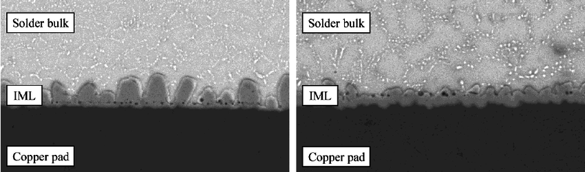
Solder joint defects often trace back to fundamental principles of soldering physics and chemistry. During soldering, the process relies on proper wetting, where molten solder spreads across surfaces to form a metallurgical bond. Wetting depends on clean surfaces, adequate flux to remove oxides, and precise thermal profiles. Standards like IPC J-STD-001H provide guidelines for acceptable solder joint formation, emphasizing the importance of temperature control and material compatibility.
For instance, solder bridging can occur if the solder's surface tension is not balanced during reflow, allowing it to flow across unintended areas. Solder balling often results from rapid outgassing of volatiles in the paste, disrupting uniform flow as per IPC-A-610H criteria. Insufficient wetting relates to poor intermetallic compound formation at the interface, often due to contamination or thermal mismatch. Engineers must consider these mechanisms when diagnosing issues, ensuring process parameters align with industry benchmarks.
Practical Solutions for Identifying Solder Problems
Diagnosing solder joint defects requires systematic inspection and testing. Below are actionable steps to identify issues effectively.
Visual Inspection
Start with a thorough visual check under magnification. Look for signs of solder bridging, such as unintended connections between pads. Check for solder balling by scanning for stray spheres on the board surface. Insufficient wetting often appears as incomplete solder coverage on leads or pads. Standards like IPC-A-600K outline acceptability criteria for visual inspection, providing clear benchmarks for defect identification.
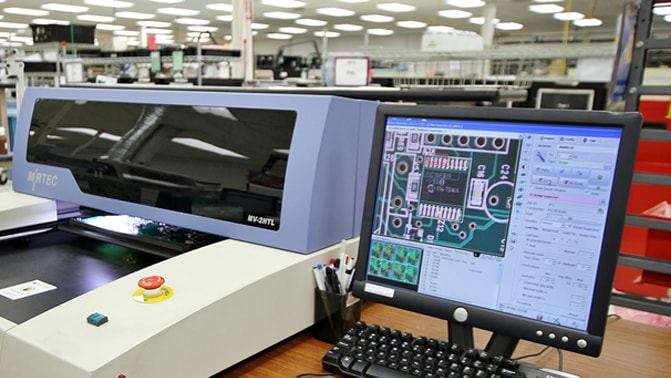
Automated Optical Inspection (AOI)
For high-volume production, AOI systems can detect defects with precision. These tools use cameras and algorithms to identify solder bridging, solder balling, and other anomalies. AOI complements manual inspection by catching subtle issues that may escape the human eye, aligning with quality control practices in IPC-6012E.
X-Ray Inspection
For hidden joints, such as those under ball grid arrays (BGAs), X-ray inspection is invaluable. It reveals voids, insufficient wetting, and solder balling beneath components. This method ensures comprehensive defect detection without destructive testing, adhering to guidelines in IPC-A-610H for non-visible joint assessment.
Electrical Testing
Functional testing and in-circuit testing (ICT) help confirm the impact of solder defects on performance. Shorts from solder bridging or open circuits from insufficient wetting become evident during electrical checks. These tests validate the integrity of joints as per IPC J-STD-001H requirements.
Best Practices for Fixing Solder Joint Defects
Once defects are identified, corrective actions must be precise to avoid further damage. Here are proven methods to address common issues.
Correcting Solder Bridging
Remove excess solder using a desoldering braid or suction tool. Ensure the area is clean before reapplying solder. Adjust stencil design or solder paste volume to prevent recurrence. Proper operator training and adherence to IPC J-STD-001H standards minimize bridging during initial assembly.
Addressing Solder Balling
Clean the affected area with a brush and isopropyl alcohol to remove stray balls. Review the reflow profile to ensure gradual heating, reducing outgassing. Use fresh solder paste and store materials properly to avoid moisture absorption. Following IPC-A-610H guidelines for paste application helps prevent this defect.
Resolving Insufficient Wetting
Rework the joint by applying flux and reheating with a soldering iron at the correct temperature. If oxidation is the cause, clean surfaces with an appropriate solvent before rework. Ensure thermal profiles match component and board specifications as outlined in IPC J-STD-020E for moisture-sensitive devices.
Process Optimization
Prevent defects by optimizing soldering parameters. Calibrate reflow ovens for consistent temperature distribution. Use high-quality flux and solder paste compatible with board materials. Regular equipment maintenance and operator training align with IPC-6012E standards, ensuring reliable outcomes.
Troubleshooting Insights for Electric Engineers
For engineers, troubleshooting goes beyond fixing individual joints. It involves analyzing patterns in defects to improve overall processes. If solder bridging recurs on specific designs, review pad spacing and stencil apertures. Persistent solder balling may indicate a need for better paste storage or reflow oven calibration. Insufficient wetting often points to material incompatibilities or inadequate cleaning protocols. Documenting defects and solutions creates a knowledge base for future projects. Adhering to standards like IPC-A-610H during analysis ensures that troubleshooting efforts meet industry expectations for quality and reliability.
Conclusion
Soldering troubleshooting is a critical skill for electric engineers working on PCB assembly. By understanding common solder joint defects like solder bridging, solder balling, and insufficient wetting, professionals can diagnose issues with precision while following PCB soldering best practices. Applying systematic inspection methods and targeted rework techniques ensures high-quality connections. Adherence to recognized standards, such as those from IPC, underpins reliable outcomes in every soldering process. With these insights, engineers can address solder problems effectively, enhancing product performance and longevity in diverse applications.
FAQs
Q1: What are the main causes of solder bridging in PCB assembly?
A1: Solder bridging often results from excess solder paste, improper stencil design, or poor component placement. Incorrect spacing between pads can also contribute. To prevent this defect, ensure precise paste application and verify design parameters. Following guidelines from industry standards like IPC J-STD-001H helps maintain control over the soldering process and avoids unintended connections.
Q2: How can engineers identify solder balling on a PCB?
A2: Solder balling appears as small, stray solder spheres on the board surface. It is visible during magnified visual inspection or through automated optical inspection systems. Causes include moisture in solder paste or improper reflow profiles. Regular checks and adherence to IPC-A-610H standards during assembly help in early detection and prevention of this issue.
Q3: What steps can be taken to fix insufficient wetting in solder joints?
A3: To address insufficient wetting, apply flux to the joint and reheat it with a soldering iron at the correct temperature. Clean oxidized surfaces before rework. Ensure proper thermal profiles as per IPC J-STD-020E to avoid recurrence. This approach strengthens the bond, ensuring reliable electrical and mechanical connections in the joint.
Q4: Why is visual inspection critical for identifying solder problems?
A4: Visual inspection under magnification is the first line of defense in spotting solder joint defects like bridging or insufficient wetting. It allows engineers to detect surface-level issues without invasive methods. Standards like IPC-A-600K provide clear criteria for acceptability, guiding engineers in maintaining quality during PCB assembly and rework processes.
References
IPC J-STD-001H — Requirements for Soldered Electrical and Electronic Assemblies. IPC, 2021.
IPC-A-610H — Acceptability of Electronic Assemblies. IPC, 2021.
IPC-A-600K — Acceptability of Printed Boards. IPC, 2020.
IPC-6012E — Qualification and Performance Specification for Rigid Printed Boards. IPC, 2020.
IPC J-STD-020E — Moisture/Reflow Sensitivity Classification for Nonhermetic Surface Mount Devices. IPC, 2014.


