Introduction
The increasing demand for compact, high-performance electronic devices has led to the widespread adoption of rigid-flex printed circuit board (PCB) technology. These innovative PCBs combine the robust interconnection capabilities of rigid boards with the flexibility of flexible circuits, offering significant advantages in space savings and complex three-dimensional packaging. However, as component densities rise and power consumption increases within these intricate designs, managing heat dissipation becomes a critical challenge. Effective thermal management in high-density rigid-flex PCB manufacturing is not just about extending component life; it is fundamental to ensuring system reliability, preventing performance degradation, and maintaining the overall integrity of the electronic assembly.
What is Rigid-Flex PCB Thermal Management and Why it Matters
Rigid-flex PCB thermal management encompasses the entire suite of design, material, and manufacturing strategies employed to efficiently dissipate heat generated by active components within a rigid-flex circuit structure. Unlike conventional rigid PCBs, the hybrid nature of rigid-flex boards introduces unique thermal pathways and material considerations that complicate heat flow.
The importance of robust thermal management cannot be overstated in high-density rigid-flex designs. Excessive operating temperatures can lead to numerous detrimental effects, including:
- Reduced Component Lifespan: High temperatures accelerate material degradation and component wear out.
- Performance Degradation: Integrated circuits may experience clock speed reductions or functionality errors when exceeding specified junction temperatures.
- Solder Joint Reliability Issues: Thermal stress from differential expansion can cause fatigue and failure of solder joints, particularly with repeated thermal cycling.
- Substrate Degradation: Overheating can lead to delamination, charring, or irreversible changes in the dielectric properties of both rigid and flexible materials.
- Signal Integrity Issues: Temperature variations can affect trace impedance and signal propagation characteristics.
Therefore, proactively addressing heat dissipation throughout the design and manufacturing phases is essential to achieve long term reliability and optimal performance of rigid-flex electronic systems.
Related Reading: 4 Pro Tips for Rigid Flex PCB Stack up Design
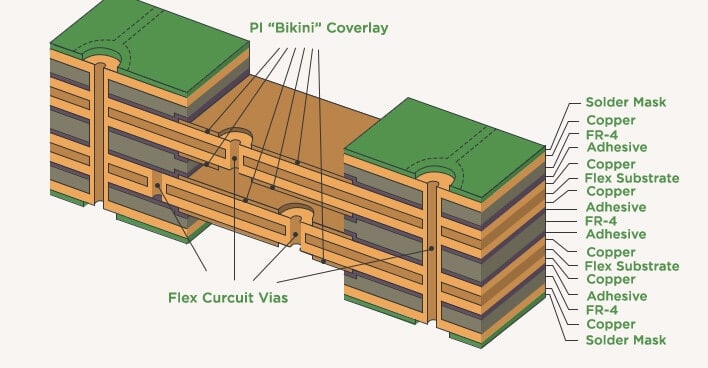
Unique Thermal Challenges of Rigid-Flex PCBs
The hybrid construction of rigid-flex PCBs presents specific thermal challenges that demand specialized consideration:
- Material Disparity: Rigid portions typically use FR-4 or similar laminates with relatively consistent thermal properties. Flexible sections, primarily polyimide films, possess different thermal conductivity and thermal expansion coefficients. This disparity can create localized hot spots and stress concentrations during thermal cycling.
- Reduced Heat Spreading in Flex Sections: The thin nature of flexible layers often limits the cross-plane thermal conductivity and lateral heat spreading capabilities compared to thicker rigid sections with larger copper planes. This can make heat removal from components directly mounted on flexible areas more difficult.
- Three-Dimensional Heat Paths: The bending and stacking of flexible layers can create complex and often constrained thermal pathways. Heat transfer might be hindered in tightly bent or encapsulated regions where airflow is restricted, leading to localized temperature increases.
- Limited Space for Cooling Solutions: High density designs inherently pack more functionality into smaller footprints, leaving minimal space for traditional external cooling solutions like large heat sinks or fans within the final product enclosure. This places greater reliance on intrinsic PCB-level thermal management.
- Manufacturing Induced Stress: The manufacturing processes for rigid-flex boards, including lamination and soldering, involve thermal cycles that can induce residual stresses due to the differing thermal expansion of materials. These stresses can be exacerbated by poor thermal design during operation.
Effective Thermal Management Techniques in Rigid-Flex PCB Manufacturing
Solving these thermal challenges requires a multi faceted approach, integrating design considerations with material selection and manufacturing process controls.
Strategic Material Selection
The choice of materials profoundly impacts thermal performance.
- High Thermal Conductivity Dielectrics: For rigid sections, selecting laminates with improved through-plane thermal conductivity can enhance heat transfer from components to internal copper planes.
- Flexible Material Considerations: While polyimide is standard for flex, its thermal properties vary. Manufacturers can choose specific polyimide formulations designed for higher thermal stability or consider alternative flexible dielectrics with enhanced thermal performance where applicable.
- Adhesives: The adhesive used to bond rigid and flexible layers, as well as to attach stiffeners, must also possess adequate thermal stability and conductivity to not impede heat flow.
Optimized Layer Stack-up Design
The PCB layer stack-up is fundamental for defining thermal pathways.
- Copper Planes for Heat Spreading: Incorporating dedicated ground and power planes, especially in rigid sections, provides excellent lateral heat spreading capabilities. These planes act as thermal conductors, distributing heat away from localized hot spots.
- Thermal Layer Placement: Strategically placing copper layers closer to heat generating components can significantly improve heat extraction. For example, a heavy copper plane directly beneath a BGA component in a rigid section can serve as an effective heat spreader.
- Balanced Stack-up: A balanced and symmetrical stack-up helps mitigate warpage and stress during thermal cycling, which indirectly contributes to maintaining consistent thermal contact.
The Role of Thermal Vias
Thermal vias are among the most effective PCB-level techniques for vertical heat transfer.
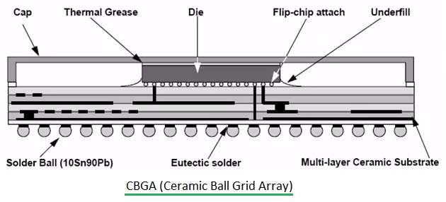
- Definition and Function: Thermal vias are non-electrical vias (or sometimes signal vias used for thermal purposes) drilled through the PCB and typically plated with copper. Their primary function is to conduct heat from a component's thermal pad, through the PCB stack-up, to internal copper planes or to the opposite side of the board for dissipation.
- Design for Rigid Sections: In rigid areas, thermal vias are typically placed directly under or around high power components. A dense array of thermal vias creates a low thermal resistance path. The IPC-2221A, Generic Standard on Printed Board Design, and IPC-2222B, Sectional Design Standard for Rigid Organic Printed Boards, recommend guidelines for via density and plating.
- Considerations for Flex Sections: While less common directly on purely flexible sections due to the thinness and bending requirements, thermal vias can be strategically employed in "flex-to-rigid" transition zones or stiffened areas of the flexible circuit to funnel heat towards the more thermally robust rigid portions.
- Filling and Capping: Thermal vias are often filled with thermally conductive epoxy or capped with solder mask to improve thermal contact with component pads and prevent solder wicking during assembly.
Related Reading: Enhancing PCB Reliability: A Guide to Thermal Vias for Heat Dissipation
Copper Weight and Trace Geometry
Heavier copper weights (e.g., 2 oz or 3 oz) on power and ground planes, especially in rigid sections, significantly improve both electrical current carrying capacity and thermal conductivity. Wider traces also offer lower electrical resistance and better heat spreading compared to thin traces. While not always feasible for fine pitch components, designers should maximize copper areas where possible to facilitate heat flow.
Component Placement Strategy
Thoughtful component placement is a primary design consideration for thermal management.
- Heat Source Isolation: High power components should be strategically placed to avoid concentrating heat in one area. Spacing them out allows for better heat dissipation.
- Proximity to Heat Sinks/Planes: Components should be placed as close as possible to thermal vias, ground planes, or areas intended for external heat sinks to minimize thermal resistance.
- Flex Region Considerations: Components generating significant heat should ideally be placed on rigid sections or on stiffened flexible areas, leveraging the better thermal dissipation capabilities of these regions.
External Cooling Solutions
While intrinsic PCB design is paramount, external cooling solutions often complement internal thermal management.
- Heat Sinks: Attaching heat sinks directly to high power components or rigid sections of the rigid-flex board provides an extended surface area for convective heat transfer to the ambient air.
- Thermal Interface Materials (TIMs): TIMs, such as thermal pads or pastes, are used between heat sources (components) and heat sinks or metal enclosures to minimize thermal contact resistance.
- Enclosure Design: The final product enclosure should be designed to facilitate airflow and heat evacuation, preventing heat buildup around the rigid-flex assembly.
Thermal Analysis and Verification
Accurate thermal analysis and verification are critical to validate design choices and predict actual thermal performance.
- Computational Fluid Dynamics (CFD) and Finite Element Analysis (FEA): Advanced software tools use CFD and FEA to simulate heat transfer within the rigid-flex PCB and the entire system enclosure. These simulations can identify potential hot spots, predict temperature distributions, and optimize thermal design before physical prototyping.
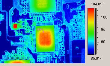
- Thermal Imaging and Testing: Infrared (IR) cameras are used to capture detailed thermal maps of assembled rigid-flex PCBs under operational conditions. This allows engineers to identify hot spots, verify simulation results, and assess the effectiveness of thermal management strategies in real world scenarios.
- Temperature Cycling and Reliability Testing: Products undergo temperature cycling tests (e.g., per JEDEC JESD22-A104E) to evaluate the long term reliability of solder joints and materials under varying thermal conditions, providing insights into the robustness of the thermal design.
Conclusion
Solving thermal management challenges in high-density rigid-flex PCB manufacturing is a complex yet crucial undertaking. By meticulously considering material properties, optimizing layer stack-ups, effectively deploying thermal vias, and strategically placing components, designers and manufacturers can build robust heat dissipation pathways into the PCB itself. Coupled with advanced thermal analysis and rigorous testing, these proactive measures ensure that rigid-flex circuits not only meet their electrical performance targets but also maintain long term reliability and functional integrity, even in the most demanding high-density applications.
FAQs
Q1: Why is thermal management more challenging in rigid-flex PCBs than rigid-only PCBs?
A1: Thermal management is more challenging in rigid-flex PCBs due to the disparity in thermal properties between rigid and flexible materials, the thinner nature of flex limiting heat spreading, and the complex three-dimensional heat paths created by bending. These factors require specialized design and manufacturing approaches.
Q2: How do thermal vias contribute to heat dissipation in rigid-flex PCBs?
A2: Thermal vias significantly contribute to heat dissipation by providing low resistance vertical pathways for heat to transfer from hot components through the PCB stack-up to internal copper planes or to the board's surface for further dissipation. They are especially effective in the rigid sections of rigid-flex designs.
Q3: What role does material selection play in rigid-flex PCB thermal management?
A3: Material selection plays a critical role in rigid-flex PCB thermal management by influencing thermal conductivity and stability. Choosing laminates with higher thermal conductivity for rigid sections and flexible materials with improved thermal resistance ensures efficient heat transfer and prevents material degradation during operation.
Q4: What standards guide thermal design for rigid-flex PCBs?
A4: Standards such as IPC-2221A, Generic Standard on Printed Board Design, which addresses general PCB design, and IPC-2223C, Sectional Design Standard for Flexible Printed Boards, which covers rigid-flex specifics, provide guidelines for material selection, layer stack-up, and component placement that indirectly impact thermal performance. JEDEC standards like JESD22-A104E also guide thermal cycling tests for reliability.
References
IPC-2221A — Generic Standard on Printed Board Design. IPC, 2003.
IPC-2222B — Sectional Design Standard for Rigid Organic Printed Boards. IPC, 2010.
IPC-2223C — Sectional Design Standard for Flexible Printed Boards. IPC, 2017.
JEDEC JESD22-A104E — Temperature Cycling. JEDEC, 2019.


