Introduction
Metal Core Printed Circuit Boards, commonly known as MCPCBs, play a critical role in modern electronics, especially in applications requiring efficient thermal management. The thickness of an MCPCB significantly influences its thermal conductivity and mechanical strength, two essential factors in PCB design. For electric engineers, understanding how MCPCB thickness affects performance is vital for optimizing designs in high power applications like LED lighting, automotive systems, and power electronics. This article explores the intricate relationship between MCPCB thickness, thermal performance, and PCB stability. By delving into the underlying principles and practical implications, engineers can make informed decisions to enhance reliability and efficiency in their designs. The discussion focuses on key PCB design factors that impact both thermal dissipation and structural integrity.
What Is MCPCB Thickness and Why It Matters
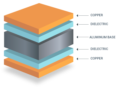
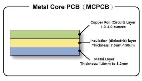
MCPCB thickness refers to the combined measurement of the metal core, dielectric layer, and copper circuitry in a metal core printed circuit board. Typically, the metal core, often aluminum or copper, forms the bulk of the thickness, providing a robust base for heat dissipation. Standard thicknesses range from 0.8 mm to 3.2 mm, depending on the application requirements. The significance of MCPCB thickness lies in its direct influence on thermal conductivity and mechanical strength. A thicker core can enhance heat spreading and structural PCB stability, while a thinner board may suffice for compact designs with lower thermal loads. For electric engineers, selecting the appropriate thickness is a balancing act between performance needs and design constraints, ensuring reliability in demanding environments.
Technical Principles of MCPCB Thickness on Thermal Performance
Thermal performance in MCPCBs is primarily governed by the ability of the metal core to conduct and dissipate heat away from critical components. The thickness of the metal core directly impacts thermal conductivity, as a thicker core provides a larger cross sectional area for heat transfer. According to fundamental heat transfer principles, increasing the thickness reduces thermal resistance, allowing heat to spread more effectively across the board. This is particularly crucial in high power applications where components generate significant heat.
The dielectric layer, although thinner, also plays a role. A thicker dielectric can increase thermal impedance, hindering heat flow to the metal core. Engineers must consider this trade off when specifying MCPCB thickness. Additionally, the choice of core material affects outcomes. Aluminum, with a thermal conductivity of approximately 200 W per meter Kelvin, benefits more from increased thickness compared to materials with lower conductivity.
Beyond the core, overall board thickness influences heat dissipation to the surrounding environment. Thicker boards can integrate with larger heat sinks or enclosures, enhancing convective cooling. However, excessively thick boards may add unnecessary weight and PCB cost without proportional thermal gains. Electric engineers must evaluate these factors during the design phase to optimize thermal performance without compromising other design goals.
Influence of MCPCB Thickness on Mechanical Stability
Mechanical stability in PCBs refers to the board's ability to withstand physical stresses, vibrations, and thermal expansion without deformation or failure. MCPCB thickness is a critical determinant of this stability. A thicker metal core enhances the board’s rigidity, reducing the risk of bending or warpage under mechanical loads. This is especially important in applications like automotive electronics, where boards are exposed to constant vibration and shock.
Thermal expansion mismatch between materials is another concern. Different layers in an MCPCB expand at varying rates when heated, inducing stress that can lead to delamination or cracking. A thicker core can mitigate this by providing greater structural support, distributing stress more evenly. Standards such as IPC-6012E outline performance specifications for rigid printed boards, including guidelines for assessing mechanical strength under thermal and physical stress.
However, increasing thickness must be balanced against practical constraints. The heavy copper pcb is heavier and may not fit within compact enclosures. They can also complicate mounting and assembly processes. Engineers need to assess the mechanical strength requirements of their specific application, ensuring that the chosen MCPCB thickness aligns with both performance and design limitations.

PCB Design Factors Influencing Thickness Selection
Selecting the appropriate MCPCB thickness involves evaluating multiple PCB design factors. These include thermal load, mechanical environment, and spatial constraints. Below is a breakdown of key considerations:
- Thermal Load: Applications with high power components require thicker cores to manage heat. For instance, LED arrays often use thicker MCPCBs to prevent overheating.
- Mechanical Environment: In harsh conditions, such as industrial or automotive settings, thicker boards provide better PCB stability against vibrations and impacts.
- Spatial Constraints: Compact devices may necessitate thinner boards to fit within limited space, even if it means reduced thermal conductivity.
- Cost and Weight: Thicker boards increase material usage, impacting both cost and weight, which can be critical in portable or cost sensitive designs.
Standards like IPC-A-600K provide acceptability criteria for printed boards, including thickness tolerances that ensure consistent performance. Engineers must align their designs with such guidelines to achieve reliable outcomes. Balancing these factors requires a deep understanding of the application’s operational demands and environmental conditions.
Practical Solutions for Optimizing MCPCB Thickness
To optimize MCPCB thickness for both thermal performance and mechanical strength, electric engineers can adopt several best practices during the design phase. First, conduct a thermal analysis to estimate the heat dissipation needs of the application. Simulation tools aligned with industry standards can predict how different thicknesses affect temperature distribution across the board.
Second, consider the mechanical requirements of the end use environment. For applications prone to vibration or shock, prioritize a thicker core to enhance PCB stability. Refer to guidelines in IPC-6012E for performance specifications that address mechanical durability in rigid boards.
Third, evaluate the dielectric layer’s impact on thermal conductivity. A thinner dielectric improves heat transfer but may compromise electrical insulation. Balance this by selecting materials with high thermal conductivity and adequate dielectric strength, adhering to standards like JEDEC J-STD-020E for moisture and reflow sensitivity classification.
Finally, prototype and test different thicknesses under real world conditions. Physical testing can reveal unforeseen issues like warpage or thermal hotspots, allowing adjustments before full scale production. These steps ensure that the selected MCPCB thickness meets both thermal and mechanical needs without unnecessary overdesign.
Troubleshooting Common Issues Related to MCPCB Thickness
In practice, incorrect MCPCB thickness can lead to performance issues. If thermal conductivity is insufficient due to a thin core, components may overheat, reducing lifespan. Engineers can address this by recalculating heat loads and increasing core thickness or integrating additional cooling solutions like heat sinks.
Conversely, excessive thickness can cause assembly challenges, especially in compact designs. If a board does not fit within the enclosure, consider reducing thickness while compensating with high conductivity materials or improved layout design to spread heat effectively.
Mechanical failures, such as cracking or delamination, often result from inadequate thickness under thermal cycling. Testing under conditions outlined in IPC-A-600K can identify weak points. Reinforcing the design with a thicker core or adjusting mounting techniques can mitigate these risks. By systematically addressing these issues, engineers ensure long term reliability and performance in their MCPCB designs.
Conclusion
MCPCB thickness is a pivotal factor in determining both thermal performance and mechanical stability in PCB design. A thicker metal core enhances thermal conductivity by reducing thermal resistance and improves PCB stability by resisting mechanical stress and thermal expansion issues. However, engineers must balance these benefits against practical constraints like weight, cost, and spatial limitations. By understanding the underlying principles and adhering to industry standards, such as those from IPC and JEDEC, optimal thickness can be selected for specific applications. Careful consideration of PCB design factors ensures that thermal and mechanical requirements are met, leading to reliable and efficient electronic systems. Through simulation, testing, and iterative design, electric engineers can achieve robust solutions tailored to their unique challenges.
FAQs
Q1: How does MCPCB thickness affect thermal conductivity in high power applications?
A1: MCPCB thickness directly impacts thermal conductivity by altering the heat transfer path through the metal core. A thicker core reduces thermal resistance, allowing better heat dissipation, which is critical for high power applications like LED lighting. Engineers can optimize designs by balancing thickness with material properties to prevent overheating, ensuring component reliability under load.
Q2: What role does MCPCB thickness play in mechanical strength for PCB stability?
A2: MCPCB thickness significantly enhances mechanical strength, contributing to PCB stability. A thicker metal core resists bending, vibration, and thermal stress, preventing warpage or cracking. This is vital in harsh environments like automotive systems. Standards like IPC-6012E provide guidelines to ensure adequate thickness for durability without overdesign.
Q3: How should engineers approach PCB design factors when selecting MCPCB thickness?
A3: When selecting MCPCB thickness, engineers must evaluate PCB design factors like thermal load, mechanical environment, and spatial constraints. High thermal loads may require thicker cores for heat dissipation, while compact designs might limit thickness. Testing and simulation aligned with industry standards help balance these factors for optimal performance.
Q4: Can MCPCB thickness impact assembly processes in PCB manufacturing?
A4: Yes, MCPCB thickness can affect assembly processes. Thicker boards may not fit in compact enclosures or may complicate mounting, while thinner boards might lack sufficient mechanical strength. Engineers should prototype different thicknesses to identify potential issues, ensuring compatibility with assembly requirements and maintaining overall design integrity.
References
IPC-6012E — Qualification and Performance Specification for Rigid Printed Boards. IPC, 2020.
IPC-A-600K — Acceptability of Printed Boards. IPC, 2020.
JEDEC J-STD-020E — Moisture/Reflow Sensitivity Classification. JEDEC, 2014.


