Introduction
For electronic hobbyists, printed circuit boards (PCBs) are the backbone of any project, whether it's a simple LED circuit or a complex microcontroller setup. However, one common issue that can halt progress is a trace short circuit, often referred to as PCB shorts. These unintended connections between traces can cause malfunctions or complete failure of a circuit. Identifying and repairing trace shorts promptly is a critical skill. This article explores how to detect PCB shorts using techniques like visual PCB inspection and multimeter PCB testing, including continuity testing. Additionally, it provides practical steps for trace short circuit repair to get your project back on track. Let's dive into understanding these faults and mastering quick fixes to ensure your circuits function as intended.
What Are PCB Shorts and Why Do They Matter?
A PCB short, or trace short circuit, occurs when two or more conductive paths on a board unintentionally connect, allowing current to flow where it shouldn't. This can happen due to manufacturing defects, physical damage, or poor design practices. For hobbyists, PCB shorts are problematic because they can lead to erratic behavior in circuits, component damage, or even safety hazards like overheating. Understanding and addressing these issues is vital to maintaining the integrity of your electronic projects. Ignoring a short can result in wasted time and resources, as the circuit won't perform as expected. By mastering detection and repair methods, hobbyists can save their boards and ensure reliable operation, making this knowledge essential for anyone working with electronics.
Causes of Trace Short Circuits
Trace shorts can arise from various sources, and recognizing these causes helps in both prevention and troubleshooting. One primary reason is manufacturing errors, such as overetching or underetching during the PCB fabrication process, which might leave unwanted copper between traces. Physical damage, like scratches or cracks on the board, can also bridge traces. Additionally, solder bridges formed during assembly can connect adjacent pads or traces. Environmental factors, such as moisture or dust accumulation, may create conductive paths over time. For hobbyists, improper handling or using low-quality materials can increase the risk of shorts. Identifying the root cause through careful inspection is the first step to effective repair, ensuring that the issue doesn't recur after a fix.
Techniques for Detecting PCB Shorts
Visual PCB Inspection
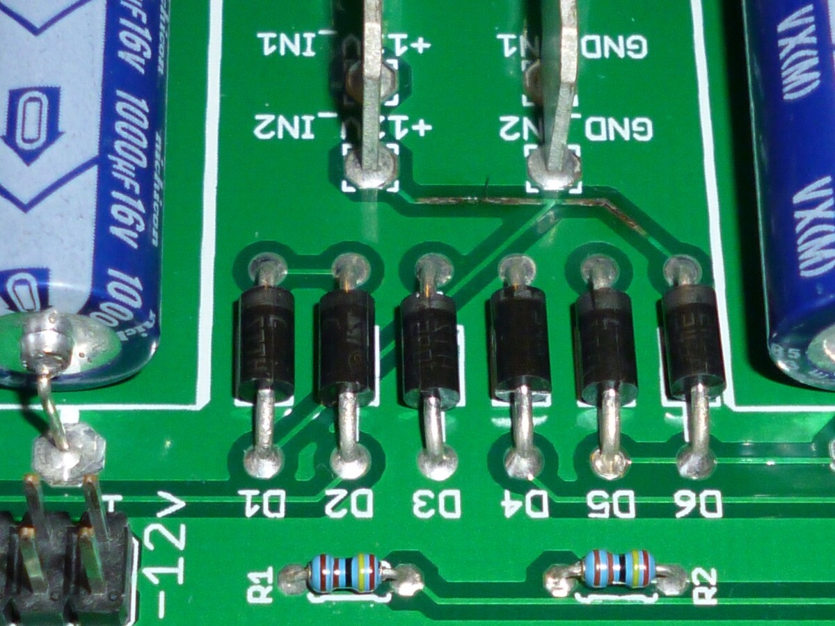
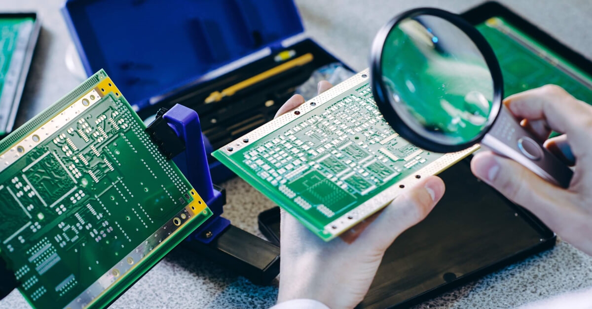
The simplest and first method to detect PCB shorts is visual inspection. Using a magnifying glass or a microscope, examine the board for obvious signs of damage, such as scratches, solder bridges, or burnt areas. Look closely at areas with dense traces or near components where shorts are more likely. Good lighting is essential to spot tiny defects. This method is non-invasive and requires no special tools beyond magnification, making it accessible for hobbyists. However, visual inspection might not reveal hidden shorts under components or within multilayer boards, so it should be paired with other techniques for comprehensive testing.
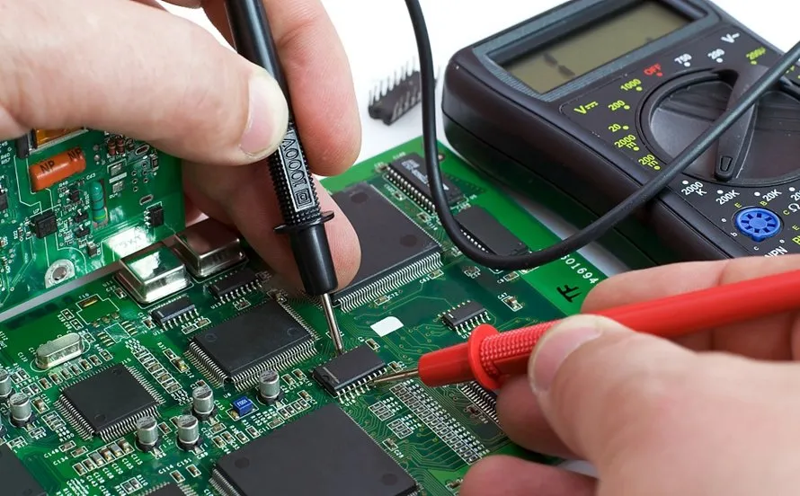
Multimeter PCB Testing with Continuity Mode
For a more reliable detection method, multimeter PCB testing using continuity mode is highly effective. Set your multimeter to the continuity setting, which beeps when a connection is detected between two points. Place the probes on suspected traces or pads. If the multimeter beeps where no connection should exist, you've found a short. Test systematically across adjacent traces and components to narrow down the location. This method is precise for surface-level shorts and works well for hobbyists with basic equipment. Ensure the board is powered off during testing to avoid damage to the multimeter or circuit.
Advanced Continuity Testing for Hidden Shorts
Continuity testing can be extended to find hidden shorts in multilayer boards or under components. If visual inspection and basic multimeter testing don't reveal the issue, isolate sections of the board by desoldering components or cutting traces temporarily. Test each segment individually with the multimeter to pinpoint the short. This approach requires patience and careful documentation to avoid further damage. While it might seem daunting for beginners, practicing on scrap boards can build confidence. Always double-check connections after repairs to confirm the short is resolved, adhering to best practices for thorough troubleshooting.
Practical Solutions for Trace Short Circuit Repair
Removing Solder Bridges
One common cause of PCB shorts is solder bridges between pads or traces. To repair this, use a desoldering braid or a solder sucker to remove excess solder. Heat the bridge with a soldering iron, then place the braid over it to absorb the molten solder. Clean the area with isopropyl alcohol and a brush to remove residue. Inspect the area visually or with a multimeter to ensure the short is gone. This method is straightforward for hobbyists and requires minimal tools, making it an accessible fix for most surface-level issues.
Cutting Damaged Traces
If a short is caused by a damaged trace connecting to another, cutting the offending section might be necessary. Use a sharp hobby knife or a small rotary tool to carefully sever the trace where the short occurs. Ensure you only cut the necessary area to avoid disrupting the circuit's functionality. After cutting, test with a multimeter to confirm the short is eliminated. This technique is useful when solder removal isn't enough, though it requires precision to prevent additional damage to the board.
Repairing with Jumper Wires
After cutting a trace or if a section is irreparable, you can bypass the damaged area using a jumper wire. Solder a thin insulated wire between the correct connection points to restore the circuit path. Keep the wire as short as possible to minimize interference. Secure it with adhesive or tape to prevent movement. Test the board afterward using continuity testing to ensure no new shorts are introduced. This repair method is practical for hobbyists and maintains circuit functionality without needing advanced tools.
Applying Protective Coating
Once a short is fixed, prevent future issues by applying a protective coating, such as conformal coating, over the repaired area. This shields the board from moisture and dust, which can cause new shorts. Use a brush or spray to apply a thin, even layer, avoiding components that need to remain exposed. Allow it to dry completely before testing the board. This step is often overlooked by hobbyists but is crucial for long-term reliability, especially in humid environments.
Troubleshooting Tips for Persistent Shorts
Sometimes, PCB shorts persist even after initial repairs. In such cases, revisit your visual PCB inspection with higher magnification to check for tiny defects. Use multimeter PCB testing across different board sections to isolate the issue. If the short remains elusive, consider thermal imaging if accessible, as it can reveal heat spots indicating a short. For hobbyists without such tools, methodical continuity testing remains the best approach. Document each step to track tested areas and avoid repetition. Persistence and systematic checking are key to resolving stubborn shorts without causing further harm to the board.
Conclusion
Dealing with PCB shorts is a common challenge for electronic hobbyists, but with the right techniques, they can be quickly identified and repaired. Through visual PCB inspection, multimeter PCB testing, and continuity testing, locating trace short circuits becomes manageable even with basic tools. Repair methods like removing solder bridges, cutting damaged traces, and using jumper wires provide practical solutions to restore functionality. By following these steps and applying protective measures, hobbyists can ensure their projects remain reliable. Mastering trace short circuit repair not only saves time and resources but also builds confidence in handling complex electronic challenges.
FAQs
Q1: How can I spot PCB shorts without advanced tools?
A1: For hobbyists, visual PCB inspection is the first step. Use a magnifying glass under good lighting to check for solder bridges, scratches, or burnt areas on traces. If nothing is visible, switch to a multimeter in continuity mode to test between traces or pads. A beep indicates a short. This combination of visual and basic testing is effective for most surface-level issues without needing specialized equipment.
Q2: What is the best way to perform multimeter PCB testing for shorts?
A2: Set your multimeter to continuity mode, ensuring the board is unpowered. Touch the probes to adjacent traces or pads where a short is suspected. If the multimeter beeps, a connection exists where it shouldn't. Test systematically across the board to locate the exact spot. This method is reliable for hobbyists and helps confirm issues found during visual inspection with minimal risk to the circuit.
Q3: How do I ensure trace short circuit repair lasts long-term?
A3: After repairing a short, clean the area with isopropyl alcohol to remove flux or debris. Apply a conformal coating to protect against moisture and dust, which can cause new shorts. Test the board with continuity testing to verify no new issues arise. Proper handling and storage also prevent physical damage, ensuring your repair holds up over time for consistent performance.
Q4: What tools are essential for continuity testing on a PCB?
A4: A digital multimeter with a continuity mode is the primary tool for testing PCB shorts. Additionally, a magnifying glass aids in visual inspection before testing. Fine-tipped probes or alligator clips can help reach tight spots on the board. These basic tools are affordable and sufficient for hobbyists to perform effective continuity testing and locate issues without advanced equipment.
IPC-A-600K — Acceptability of Printed Boards. IPC, 2020.
IPC-6012E — Qualification and Performance Specification for Rigid Printed Boards. IPC, 2017.


