Introduction
Metal Core Printed Circuit Boards, often referred to as MCPCBs, are essential in applications requiring efficient heat dissipation, such as LED lighting, power electronics, and automotive systems. These boards use a metal substrate, typically aluminum or copper, to enhance thermal management. However, MCPCB manufacturing issues like delamination, warpage, poor thermal conductivity, and short circuits can compromise performance and reliability. For electrical engineers, understanding and resolving these defects is critical to ensuring product quality and longevity. This guide explores the root causes of common MCPCB defects and offers practical troubleshooting strategies. By addressing these challenges, engineers can optimize designs and manufacturing processes to meet stringent industry standards and application demands.
What Are Metal Core PCBs and Why Do Defects Matter
Metal Core PCBs are specialized circuit boards with a metal base layer that acts as a heat sink, distinguishing them from traditional FR4 PCB. The metal core, often aluminum due to its cost-effectiveness and thermal properties, is bonded with a dielectric layer and copper circuitry. This construction enables superior heat dissipation, making MCPCBs ideal for high-power applications. However, manufacturing defects in MCPCBs can lead to significant issues. Delamination weakens structural integrity, warpage affects assembly precision, poor thermal conductivity reduces heat dissipation efficiency, and short circuits cause electrical failures. For electrical engineers, these defects not only impact functionality but also increase production costs and delay project timelines. Addressing these problems is vital to maintaining reliability and meeting performance expectations in demanding environments.
Common MCPCB Manufacturing Defects and Their Causes
Delamination in MCPCBs
Delamination occurs when layers of the MCPCB separate, often between the metal core and the dielectric layer or between the dielectric and copper foil. This defect compromises structural stability and thermal performance. Common causes include inadequate bonding during lamination, moisture absorption in materials, and thermal stress from mismatched coefficients of thermal expansion among layers. Improper curing of the dielectric material can also weaken adhesion. According to industry guidelines like IPC-6012E, delamination is often linked to process control issues during manufacturing, such as inconsistent pressure or temperature profiles.
Warpage Issues
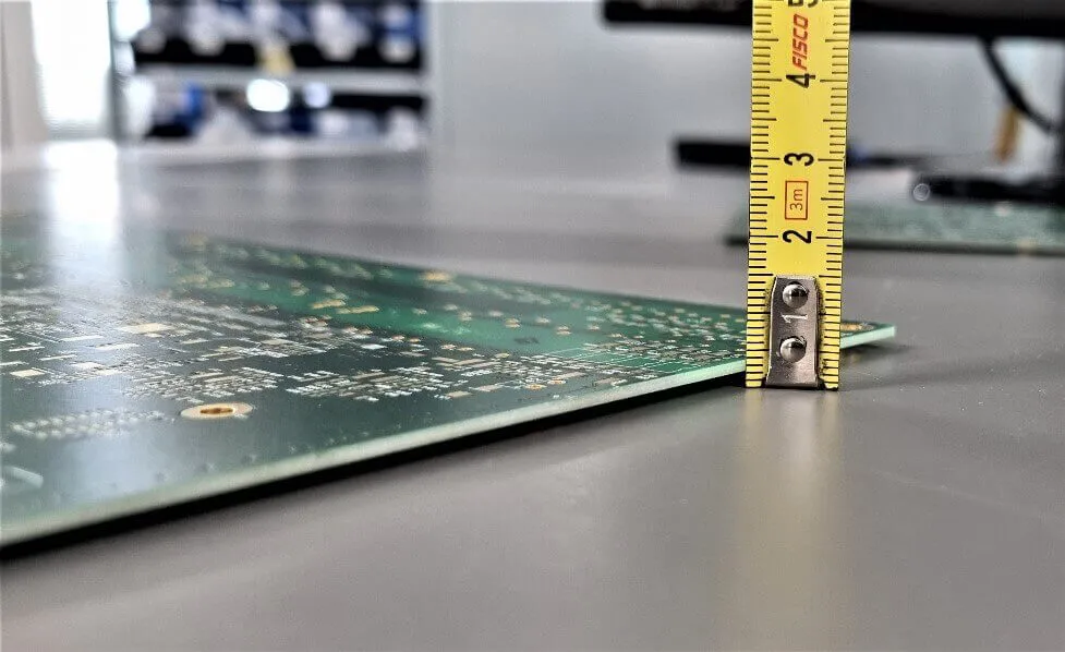
Warpage refers to the unintended bending or twisting of the MCPCB, making it difficult to assemble components accurately. This defect arises from uneven stress distribution during manufacturing, often due to asymmetric layer stacking or differences in thermal expansion rates between the metal core and other materials. Insufficient cooling after lamination or improper handling can exacerbate the issue. Warpage not only affects mechanical fit but also strains solder joints, leading to reliability concerns.
Related Reading: Minimizing Warpage in Multilayer PCB Manufacturing: Causes and Cures
Poor Thermal Conductivity
Poor thermal conductivity in MCPCBs defeats their primary purpose of efficient heat dissipation. This issue often stems from low-quality dielectric materials with inadequate thermal transfer properties or inconsistent thickness, which creates thermal barriers. Air voids or impurities trapped during lamination can further hinder heat flow from the circuitry to the metal core. For engineers, identifying this defect requires evaluating material specifications and manufacturing consistency to ensure thermal performance aligns with design requirements.
Short Circuits in MCPCBs
Short circuits occur when unintended electrical connections form between conductive paths, often due to manufacturing flaws. In MCPCBs, this can result from insufficient dielectric thickness, copper residue from etching processes, or damage during drilling and handling. Contamination, such as dust or moisture, can also bridge conductive areas. Short circuits lead to system failures and pose safety risks, making early detection and prevention critical for maintaining electrical integrity.
Practical Solutions for Troubleshooting MCPCB Defects
Addressing Delamination
To mitigate delamination, engineers should focus on optimizing the lamination process. Ensuring uniform temperature and pressure during bonding, as outlined in IPC-6012E, helps achieve strong interlayer adhesion. Pre-baking materials to remove moisture before lamination prevents trapped humidity from causing separation. Selecting dielectric materials with compatible thermal expansion properties relative to the metal core reduces stress during temperature cycles. Regular inspection using non-destructive testing methods, such as ultrasonic scanning, can detect early signs of delamination for corrective action.
Correcting Warpage
Preventing warpage starts with balanced design and process control. Engineers should aim for symmetrical layer stacking to minimize stress imbalances. Controlling cooling rates after lamination avoids rapid thermal contraction that induces bending. Adhering to guidelines in IPC-A-600K for acceptable board flatness ensures warpage stays within tolerable limits. Using fixtures during manufacturing to hold the board flat can also help. For existing warpage, controlled heating and pressing may restore flatness, though caution is needed to avoid further damage.
Improving Thermal Conductivity
Enhancing thermal conductivity requires careful material selection and process optimization. Engineers should choose dielectric layers with high thermal transfer ratings, verified through material datasheets and testing. Ensuring consistent dielectric thickness during manufacturing prevents uneven heat distribution. Minimizing air voids through proper vacuum lamination techniques is essential. Thermal imaging can identify hot spots indicative of poor conductivity, guiding targeted improvements. Compliance with standards like IPC-6012E for material performance ensures reliability in heat dissipation.
Preventing Short Circuits
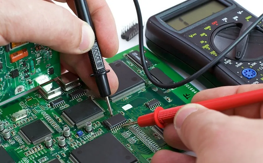
Preventing short circuits involves rigorous process control and inspection. Maintaining adequate dielectric thickness as per design specifications avoids breakdown under voltage stress. Thorough cleaning after etching removes copper residues that could cause unintended connections. Visual and automated optical inspections, aligned with IPC-A-600K, help detect defects like scratches or contamination early. Electrical testing for continuity between traces confirms insulation integrity. Proper handling and storage in controlled environments reduce risks of moisture or particulate contamination.
In-Depth Troubleshooting Insights for Electrical Engineers
For electrical engineers tackling MCPCB manufacturing issues, a systematic approach is crucial. Start by documenting the defect symptoms, such as visible delamination or measurable warpage, to narrow down potential causes. Use diagnostic tools like thermal cameras for conductivity issues or microscopes for inspecting short circuit paths. Cross-reference findings with manufacturing logs to identify deviations in temperature, pressure, or material handling. Implementing corrective actions should align with recognized standards like IPC-6012E to ensure consistency. For instance, if delamination is detected, review lamination parameters and material storage conditions. Collaboration with manufacturing teams to adjust processes, such as extending pre-bake times or refining cooling profiles, often yields better outcomes. Keeping detailed records of troubleshooting efforts helps build a knowledge base for future defect prevention.
Conclusion
Metal Core PCB manufacturing defects like delamination, warpage, poor thermal conductivity, and short circuits pose significant challenges for electrical engineers. Understanding the root causes, from material mismatches to process inconsistencies, is the first step toward effective troubleshooting. By implementing practical solutions such as optimized lamination, balanced design, and rigorous inspection, engineers can mitigate these issues and enhance board reliability. Adhering to industry standards ensures that corrective actions are both effective and repeatable. With a proactive approach to identifying and resolving MCPCB manufacturing issues, engineers can achieve superior thermal performance and electrical integrity in their designs, supporting the success of high-power applications.
FAQs
Q1: What are the primary causes of delamination in MCPCB manufacturing?
A1: Delamination in MCPCBs often results from inadequate bonding during lamination, moisture trapped in materials, or thermal stress due to mismatched expansion coefficients. Poor process control, like uneven pressure or temperature, also contributes. Following standards like IPC-6012E for lamination parameters and pre-baking materials to eliminate moisture can significantly reduce this defect, ensuring robust layer adhesion.
Q2: How can warpage in metal core PCBs be minimized during production?
A2: Warpage in MCPCBs can be minimized by designing symmetrical layer stacks and controlling cooling rates after lamination. Using fixtures to maintain flatness during manufacturing helps manage stress. Adhering to IPC-A-600K guidelines for acceptable board flatness ensures consistency. Regular monitoring of process parameters prevents uneven thermal contraction, preserving board integrity for assembly.
Q3: Why does poor thermal conductivity occur in MCPCBs, and how can it be fixed?
A3: Poor thermal conductivity in MCPCBs often stems from low-quality dielectric materials or inconsistent layer thickness, hindering heat transfer. Air voids from improper lamination also contribute. Selecting high-performance dielectrics and optimizing vacuum lamination processes can improve conductivity. Thermal imaging identifies problem areas, allowing targeted fixes to ensure efficient heat dissipation as per design needs.
Q4: What steps can prevent short circuits in MCPCB manufacturing?
A4: Preventing short circuits in MCPCBs involves ensuring adequate dielectric thickness and thorough cleaning after etching to remove copper residues. Regular inspections, guided by IPC-A-600K, detect contamination or damage early. Electrical testing verifies insulation integrity between traces. Controlled handling and storage minimize risks of moisture or dust, safeguarding electrical performance during production.
References
IPC-6012E — Qualification and Performance Specification for Rigid Printed Boards. IPC, 2020.
IPC-A-600K — Acceptability of Printed Boards. IPC, 2020.


