Introduction
Printed circuit boards form the backbone of modern electronics, enabling complex circuits in compact designs for countless applications. For electrical engineers, achieving a functional and reliable layout hinges on precise manufacturing processes, with PCB drilling standing as a critical step. Drill holes in PCB board fabrication are not mere perforations; they facilitate electrical connections, component mounting, and structural integrity. Ensuring these holes are accurate and of good quality directly impacts the performance of the final product. This article explores the pivotal role of drill holes in PCB board fabrication, detailing their technical significance, best practices for precision, and their influence on layout success. Aimed at engineers and technical professionals, this discussion provides insights into optimizing drilling for effective circuit design.
What is PCB Drilling and Why Does It Matter?
PCB drilling is a fundamental process in printed circuit board manufacturing, where holes are created in the board material to serve multiple purposes. These holes, often referred to as vias or through-holes, connect different layers of a multilayer board, allow component leads to pass through, or provide mounting points for hardware. The role of drill holes in PCB board fabrication is central to ensuring electrical conductivity and mechanical stability.
The importance of drilling lies in its direct effect on circuit functionality. Without accurately placed and sized holes, electrical signals cannot travel between layers, components cannot be securely mounted, and the board may fail under operational stress. Poor drilling quality can lead to issues like misalignment, insufficient connectivity, or structural weaknesses, compromising the entire design. For electrical engineers, understanding this process ensures that the planned layout translates into a working product that is accurate and of good quality.
Related Reading: Why is PCB Drilling Essential To Making Your Planned PCB Layout Work?
Technical Principles of PCB Drilling
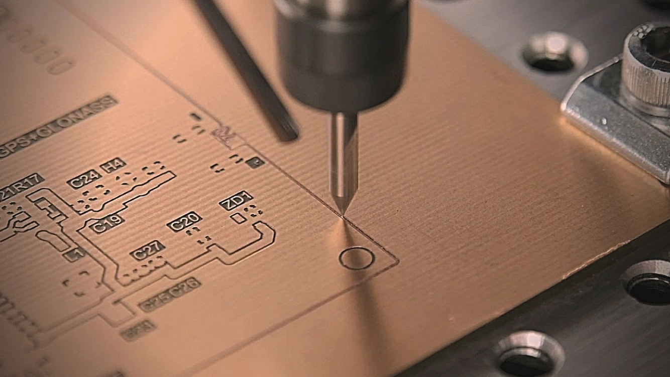
The drilling process in PCB board fabrication involves creating holes using specialized equipment, often computer numerical control (CNC) machines, to achieve precision. These machines use high-speed spindles and micro-drills, typically made of durable materials like tungsten carbide, to penetrate the board substrate, which may include fiberglass, epoxy, or other composites.
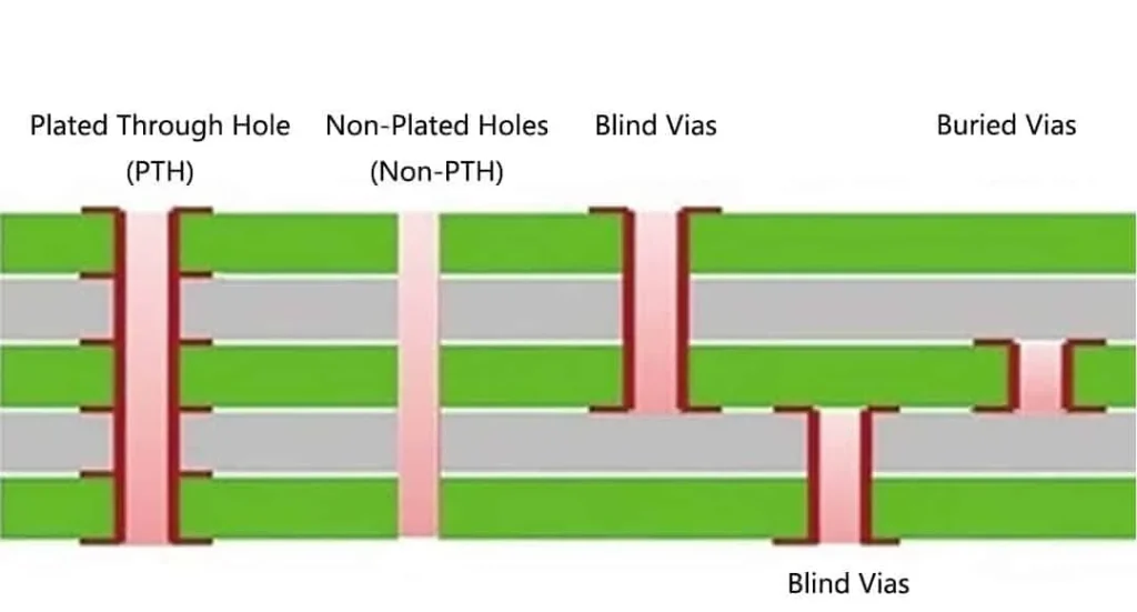
Holes in a printed circuit board serve distinct functions based on their type. Plated through-holes (PTHs) are coated with conductive material, usually copper, to establish electrical connections between layers, as outlined in standards like IPC-6012E. Non-plated through-holes (NPTHs) are used for mechanical purposes, such as mounting screws or aligning the board during assembly. Vias, a subset of PTHs, include through-vias, blind vias, and buried vias, each designed for specific layer connectivity in multilayer boards.
The precision of drilling affects signal integrity and manufacturing yield. Misaligned or oversized holes can disrupt trace routing, while undersized holes may prevent component insertion. Additionally, drilling generates heat and stress, which, if not managed, can cause delamination or microcracks in the board material. Standards such as IPC-A-600K emphasize acceptable tolerances for hole size, position, and wall quality to mitigate these risks.
Factors Affecting Drilling Accuracy and Quality
Achieving holes that are accurate and of good quality in PCB board fabrication requires attention to several factors. First, the choice of drill bit and spindle speed influences hole precision. Smaller diameter drills, often below 0.3 millimeters for micro-vias, demand higher speeds and lower feed rates to avoid breakage or deflection. Second, the board material composition affects drilling dynamics. Harder substrates require slower drilling to prevent tool wear, while softer materials may need faster speeds to avoid burr formation.
Another critical factor is the drill entry and exit strategy. Using entry materials, like phenolic or aluminum sheets, helps stabilize the drill and reduce burrs on the board surface. Exit burrs, if not controlled, can interfere with subsequent processes like plating, as noted in IPC-6012E guidelines. Additionally, proper machine calibration and regular tool maintenance ensure consistent hole placement and size, aligning with tolerances specified in IPC-A-600K.
Thermal management during drilling is also vital. Excessive heat can degrade the board material or cause resin smear inside holes, hindering conductivity during plating. Cooling techniques, such as air or liquid coolants, are often employed to maintain optimal conditions. For electrical engineers, recognizing these variables aids in specifying design parameters that align with manufacturing capabilities.
Related Reading: Selecting the Ideal PCB Drill Bit for Precision and Reliability
Practical Solutions for Effective PCB Drilling
To ensure drilling supports the planned PCB layout, engineers can adopt several best practices during design and collaboration with manufacturing teams. Start by defining hole specifications clearly in design files. Include precise diameters, tolerances, and whether holes are plated or non-plated, adhering to standards like IPC-6012E. This clarity prevents misinterpretation during fabrication.
Consider minimizing the variety of hole sizes in a single design. Using uniform hole dimensions reduces tool changes during drilling, lowering the risk of errors and speeding up production. When multiple sizes are unavoidable, group similar holes in specific board areas to streamline the process. Additionally, ensure adequate spacing between holes and traces to avoid structural weakening or electrical interference.
Collaboration with fabricators is essential for optimizing drilling. Provide detailed drill drawings or files that specify hole locations and types, as these guide the CNC programming. Review the manufacturer’s drilling capabilities, such as minimum hole size or aspect ratio limits, to align design expectations with production realities. For high-density layouts, consider advanced drilling techniques like laser drilling for micro-vias, which offers greater precision for smaller holes.
Finally, incorporate design for manufacturability (DFM) checks to identify potential drilling issues before fabrication. Software tools can simulate hole placement and flag violations of spacing or tolerance rules. By prioritizing these steps, engineers ensure that drill holes in PCB board fabrication meet the necessary standards and support the intended layout functionality.
Impact of Drilling on PCB Layout Success
The role of drill holes in PCB board fabrication extends beyond mere creation of openings; it directly shapes the success of the planned layout. Accurate drilling ensures that vias connect layers as intended, maintaining signal integrity across the circuit. For multilayer boards, precise blind and buried vias are critical to routing signals in confined spaces without interference.
Mechanically, well-drilled holes secure components and hardware, preventing movement or failure during operation. Mounting holes, if misaligned, can lead to assembly issues or stress points that compromise board durability. Electrically, poor hole quality, such as rough walls or inadequate plating, can increase resistance or cause intermittent connections, leading to circuit malfunctions.
For electrical engineers, the drilling process also influences design flexibility. Properly executed holes allow for tighter component placement and more complex routing, enabling compact and efficient layouts. Conversely, drilling errors can force design revisions or costly rework, delaying project timelines. Thus, prioritizing drilling precision is integral to translating a theoretical layout into a functional printed circuit board.
Conclusion
PCB drilling stands as a cornerstone in printed circuit board manufacturing, directly impacting the feasibility and performance of any planned layout. The role of drill holes in PCB board fabrication encompasses electrical connectivity, mechanical stability, and overall design integrity. By understanding the technical principles, addressing factors that affect accuracy, and implementing best practices, electrical engineers can ensure holes are accurate and of good quality. This attention to detail bridges the gap between design intent and manufactured reality, enabling reliable and efficient circuits. As layouts grow more complex with advancing technology, mastering the nuances of drilling remains essential for successful PCB development.
FAQs
Q1: What is the primary role of drill holes in PCB board fabrication?
A1: Drill holes in PCB board fabrication serve to connect layers electrically through vias, mount components, and provide structural support via hardware holes. Their precision ensures signal integrity and mechanical stability, directly affecting circuit performance. Standards like IPC-6012E guide acceptable hole specifications to maintain quality during manufacturing.
Q2: How does drilling accuracy impact a printed circuit board layout?
A2: Drilling accuracy in a printed circuit board determines whether vias and mounting holes align with the design, ensuring proper connectivity and component placement. Inaccurate holes can disrupt signal paths or weaken the board, leading to failures. Adhering to tolerances in IPC-A-600K is crucial for layout success.
Q3: Why is achieving accurate and of good quality holes critical in PCB fabrication?
A3: Accurate and good quality holes in PCB fabrication prevent electrical issues like poor connectivity and mechanical failures during assembly or operation. They ensure reliable signal transmission and secure component mounting. Following standards such as IPC-6012E helps maintain consistency and performance in the final product.
Q4: What steps can engineers take to improve drilling in PCB board fabrication?
A4: Engineers can improve drilling in PCB board fabrication by specifying clear hole requirements, minimizing size variations, and using DFM checks to spot issues. Collaborating with fabricators to understand their capabilities and providing detailed drill files ensures precision. Following IPC-A-600K guidelines supports quality outcomes.
References
IPC-6012E — Qualification and Performance Specification for Rigid Printed Boards. IPC, 2020.
IPC-A-600K — Acceptability of Printed Boards. IPC, 2020.


