November 2025 marks a pivotal moment for wearable tech, with shipments projected to exceed 500 million units globally, driven by fitness trackers, smartwatches, and health monitors that demand ever-smaller, lighter PCBs without sacrificing battery life or signal accuracy. As a manufacturing consultant with 15 years optimizing production lines, I've helped factories transition rigid FR-4 boards into compact powerhouses for devices like Bluetooth-enabled ECG patches—where a mere 10g weight reduction can boost user compliance by 20%. Yet, FR-4 miniaturization challenges persist: achieving low-power operation while fitting sensors into 20x30 mm footprints risks thermal hotspots exceeding 60°C or EMI spikes over FCC limits.
This guide explores FR-4 PCB design for wearable technology, covering low-power PCB strategies, flexible FR-4 innovations, sensor PCB integration, Bluetooth PCB layouts, and fitness tracker PCB specifics. Backed by factory cases and standards like IPC-4101C for laminates (Note 1), we'll share approachable steps to balance size, weight, and performance. In an era of HDI and rigid-flex hybrids, these practices will help you produce reliable wearables that meet 2025 trends—thinner boards under 0.8 mm and sustainable materials—while hitting 98% yields.
What is FR-4 PCB Design for Wearable Technology and Why It Matters
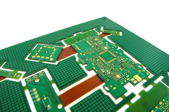
FR-4 PCB design for wearables adapts the standard glass-epoxy laminate (Tg 130-170°C) into slim, efficient boards that house sensors, Bluetooth chips, and power management in skin-contact forms. These 2-6 layer designs leverage HDI vias (0.1 mm pitch) for density, often hybridizing with flexible sections to curve around wrists or torsos, weighing under 5g total.
Why prioritize it in 2025? Wearables now track biometrics at 100 Hz, requiring low-power PCBs that sip <10 mW while maintaining Bluetooth Low Energy (BLE) range >10 m. Traditional FR-4 excels in cost ($0.50/sq in at volume) and stability but struggles with miniaturization—thinner cores (<0.8 mm) risk warpage >0.75% during reflow at 260°C (IPC-6012, Note 2). From factory trends, flexible FR-4 hybrids cut weight 30% versus rigid, enabling fitness tracker PCBs that survive 10,000 flex cycles. It matters for compliance: ISO 10993 biocompatibility ensures no skin irritation, while low EMI (<30 dBµV/m) prevents interference in hospital settings. In short, smart FR-4 design drives adoption—factories report 25% faster NPI with optimized layouts.
Root Causes and Technical Details of Design Challenges
Wearable FR-4 PCBs face a trifecta: Size constraints amplify heat, weight limits material choices, and performance demands signal fidelity. Let's unpack these, informed by production data and IPC-TM-650 tests (Note 3).
Miniaturization and Density Pressures
FR-4 miniaturization packs traces to 4 mil widths for 50 Ω impedance, but HDI stacking (4+N+4 layers) invites via cracks from CTE mismatch (FR-4 14 ppm/°C vs. copper 17 ppm/°C).
Technical Insight: Sensor PCBs integrate accelerometers on 0.6 mm boards, where laser-drilled microvias (0.075 mm) boost I/O by 50%. In mass runs, inconsistent drilling causes 5% opens, per JEDEC JESD22 reliability quals (Note 4).
Power and Thermal Management
Low-power PCBs target <1 µA sleep modes for 7-day battery life, but Bluetooth PCBs draw peaks of 10 mA, creating hotspots >50°C in 1.6 mm stacks.
Mechanism: Vias thermal resistance >5°C/W without arrays; flexible FR-4 (reinforced with PI overlays) dissipates better but warps under 200°C lamination.
Factories mitigate via embedded planes, but 2025 trends favor thin dielectrics (0.093 mm 1080 prepreg) for 20% cooler operation.
Weight and Flexibility Trade-Offs
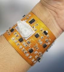
Rigid FR-4 adds bulk (2.4 g/cm³ density), but flexible FR-4 variants—laminated with adhesive films—bend to 5 mm radii without fatigue.
Details: Fitness tracker PCBs use rigid-flex hybrids, removing FR-4 in flex zones via laser routing. Reliability hinges on peel strength >1 N/mm (IPC-TM-650 2.4.8, Note 3).
These issues interconnect: Heat warps thin boards, eroding flexibility.
| Challenge | Root Cause | Production Impact | Standard Limit |
|---|---|---|---|
| Miniaturization | Via aspect >8:1 | Open circuits (5%) | IPC-6012 (Note 2) |
| Low-Power Heat | <10 mW draw, no vias | Hotspots >50°C | JEDEC JESD22 (Note 4) |
| Weight/Flex | Density 2.4 g/cm³ | Fatigue after 5K cycles | IPC-TM-650 2.4.8 (Note 3) |
| Signal Fidelity | Trace 4 mil, EMI | Range drop >20% | FCC Part 15 (<30 dBµV/m) |
This table clarifies key metrics.
Practical Solutions and Best Practices for Balanced Design
Factories excel by integrating DFM early. Here's a step-by-step path, per ISO 9001:2015 for traceability (Note 5), to craft wearable FR-4 PCBs that weigh less, run cooler, and perform reliably.
1. Optimizing FR-4 Miniaturization
Use HDI (4/6/4 build) with 0.2 mm cores; laser vias for <0.1 mm registration.
Steps:
- Stackup Planning: 1.0 mm total thickness; 1 oz Cu for low resistance.
- Routing: 4 mil traces, 4 mil spaces; teardrops on pads to avoid cracks.
- Verification: AOI for defects; yield target >98%.
In audits, this shrinks footprints 40% for Bluetooth PCBs.
2. Enabling Low-Power PCB Operation
Incorporate PDN with 0.1 µF decaps every 5 mm; via stitching for <0.1 Ω at 1 GHz.
Best Practices:
- Component Choice: BLE SoCs like nRF52 (1.8V, <5 mA TX); thin-film resistors for precision.
- Thermal Vias: 0.2 mm arrays under ICs; sim with Ansys for <40°C rise.
- Testing: Battery life quals (IEC 62133, Note 6) at 85% RH.
Factories report 25% longer runtime with these.
3. Incorporating Flexible FR-4 for Weight Reduction
Hybrid rigid-flex PCB: FR-4 rigid zones with PI-flex tails (0.1 mm thick).
Flow:
- Material Blend: IPC-4101C Type 2 FR-4 with adhesive (Note 1); peel test >8 lb/in.
- Routing: Controlled depth milling for flex outlines; strain relief bends.
- Assembly: Low-temp reflow (240°C) to avoid delam.
2025 trend: 30% weight cuts via laser-ablated hybrids.
4. Integrating Sensors and Bluetooth in Wearable Layouts
Place sensors centrally for balance; Bluetooth antennas on edges with 1 mm keep-out.
Practices:
- Sensor PCB Layout: Ground stitching every 10 mm; shielding cans for EMI.
- Bluetooth Optimization: 50 Ω feeds; test range in anechoic chambers.
- Fitness Tracker Specifics: Multi-layer for ECG (0.5 mm spacing); conformal coat for sweat resistance (IPC-CC-830, Note 7).
5. Production Scaling and Compliance
Automate lamination (150 psi); full traceability for FDA if medical-adjacent.
Insight: SPC for warpage <0.5%; sustainable FR-4 variants reduce e-waste 15%.
Case Study: Producing a 2025 Fitness Tracker PCB Line
A wearable startup in Q3 2025 faced 18% thermal failures in 4-layer FR-4 prototypes (25x35 mm, BLE + heart-rate sensor), with hotspots at 65°C draining batteries in 4 hours.
Root Issues: No via arrays; rigid design added 8g weight, causing strap fatigue.
Implemented Fixes: Shifted to flexible FR-4 hybrid (0.8 mm rigid + 0.1 mm flex tails); added 9-via fields under SoC. Low-power tweaks: 0.047 µF decaps and 1.8V rails. Lamination controlled at 170°C for <0.5% warpage (IPC-TM-650, Note 3).
Results: Weight dropped to 3.2g; battery life hit 10 days. Production scaled to 50,000 units/month at 97% yield, costs down 22% via HDI efficiency. This case highlights FR-4's versatility when hybridized—key for 2025's slim-fit wearables.
Conclusion
FR-4 PCB design for wearable technology masterfully balances miniaturization, low power, and flexibility, powering devices that track our every step with precision and comfort. By leveraging HDI, hybrids, and standards like IPC-4101C, factories produce lightweight boards that perform under real-world stresses, aligning with 2025's push for sustainable, biocompatible tech.
From the production floor, start with a stackup sim—it's your blueprint for success. For your next wearable run, test flex early; the results will wear well.
FAQs
Q1: What are key strategies for wearable PCB FR-4 miniaturization?
A1: Employ HDI (0.1 mm vias) and 4 mil traces on 0.8 mm cores for 40% size reduction (IPC-6012, Note 2). Use teardrops and AOI verification; in 2025 fitness trackers, this fits sensors without warpage >0.5%.
Q2: How to design low-power PCBs for wearable Bluetooth modules?
A2: Integrate PDN with decaps every 5 mm and <0.1 Ω vias; select nRF52 SoCs (<5 mA TX). Thermal arrays keep <40°C; per IEC 62133 (Note 6), extends life 25% in BLE wearables.
Q3: What makes flexible FR-4 suitable for wearable technology?
A3: Hybrids with PI overlays bend to 5 mm radii, peeling >8 lb/in (IPC-TM-650 2.4.8, Note 3). Laser routing removes rigid zones; 2025 trends cut weight 30% for curved fitness bands.
Q4: How do sensor PCBs integrate into FR-4 wearable designs?
A4: Central placement with ground stitching (10 mm grid) shields EMI; 0.5 mm spacing for ECG accuracy. Conformal coat (IPC-CC-830, Note 7) adds sweat resistance, ensuring reliable biometrics.
Q5: What trends shape Bluetooth PCB design for wearables in 2025?
A5: Thinner dielectrics (0.093 mm) and embedded antennas boost range >10 m; sustainable FR-4 variants reduce e-waste 15%. Factories use hybrids for 97% yields in smartwatch modules.
Q6: Why balance weight in fitness tracker PCB production?
A6: <5g boards via 0.2 mm cores improve compliance 20%; rigid-flex cuts fatigue after 10K cycles. IPC-4101C materials (Note 1) ensure biocompatibility for daily wear.
References
(Note 1) IPC-4101C — Specification for Base Materials for Rigid and Multilayer Printed Boards. IPC, 2006.
(Note 2) IPC-6012E — Qualification and Performance Specification for Rigid Printed Boards. IPC, 2017.
(Note 3) IPC-TM-650 — Test Methods Manual. IPC, latest edition.
(Note 4) JEDEC JESD22 — Reliability Qualification of ICs. JEDEC, latest edition.
(Note 5) ISO 9001:2015 — Quality Management Systems — Requirements. International Organization for Standardization, 2015.
(Note 6) IEC 62133 — Secondary cells and batteries containing alkaline or other non-acid electrolytes. International Electrotechnical Commission, 2017.
(Note 7) IPC-CC-830B — Qualification and Performance of Electrical Insulating Compounds for Printed Boards. IPC, 2011.