Introduction
As 5G infrastructure, millimeter-wave radar, high-speed SerDes above 28 Gbps, and satellite communication systems become mainstream, signal frequencies in multilayer PCBs now routinely exceed 20 GHz and often reaching 110 GHz in automotive 77 GHz radar modules. At these frequencies, ordinary FR-4 exhibits unacceptable insertion loss, phase distortion, and impedance variation. Choosing the correct materials for high-frequency PCB directly determines whether a design meets eye-diagram specifications, bit-error-rate targets, and thermal reliability requirements. This guide compares the key electrical, thermal, and mechanical properties of commercial low-loss laminates and provides practical selection criteria for multilayer high-frequency designs.
Why FR-4 Fails at RF and Microwave Frequencies
Standard FR-4 (woven glass + difunctional epoxy) has:
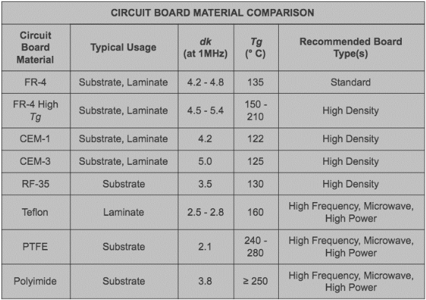
- Dielectric constant (Dk) 4.0–4.6 with ±10% lot-to-lot variation
- Dissipation factor (Df) 0.015–0.025 at 10 GHz
- Dk increases 8–12% after moisture absorption
- Rough woven-glass reinforcement causes Dk anisotropy
Above 6 GHz these properties create excessive insertion loss (typically >0.5 dB/inch at 28 GHz), severe skew in differential pairs, and unacceptable phase instability over temperature.
Key Electrical Parameters for High-Frequency PCB Materials
| Parameter | Symbol | Typical FR-4 | Low-Loss Hydrocarbon | PTFE-Based | Importance |
|---|---|---|---|---|---|
| Dielectric constant @10 GHz | Dk | 4.2–4.5 | 3.0–3.7 | 2.1–3.5 | Impedance control, phase velocity |
| Dissipation factor @10 GHz | Df | 0.020 | 0.0015–0.004 | 0.0009–0.0025 | Insertion loss |
| Dk process variation | ± | 0.10 | 0.02–0.05 | 0.02 | Manufacturing repeatability |
| Moisture absorption | % | 0.3–0.5 | <0.1 | <0.05 | Dk stability |
| Dk temperature coefficient | ppm/°C | –150 | –50 to –120 | +50 to –200 | Phase stability |
Major Classes of High-Frequency Laminates
1. PTFE-Based Materials
- Lowest Df (0.0009–0.0022)
- Most stable Dk across frequency and temperature
- Difficult to process in multilayer (requires special bonding films, plasma treatment)
- Highest cost
- Typical applications: space-grade, mm-wave phased arrays, 77–81 GHz radar
2. Thermoset Hydrocarbon with Ceramic Fillers
- Dk 3.0–3.7, Df 0.0015–0.004
- Excellent multilayer processability (similar to FR-4)
- Good copper adhesion with low-profile foils
- Widely used in 5G base stations, 28–56 Gbps SerDes backplanes
3. PPE-Based (Polyphenylene Ether) Blends
- Dk ≈ 3.4, Df ≈ 0.004–0.008
- Lower cost than pure hydrocarbon/ceramic
- Easier drilling and plating than PTFE
- Common in enterprise switches and routers
4. Hybrid Constructions
Combine PTFE cores for RF layers with hydrocarbon or PPE prepreg in digital layers to balance cost and performance. Most 5G AAU boards and automotive radar sensors use hybrid stackups.
Practical Material Selection Flow for Multilayer High-Frequency PCBs
- Determine maximum operating frequency and acceptable insertion loss budget → >40 GHz → PTFE or ceramic-filled hydrocarbon → 10–40 GHz → low-loss thermoset hydrocarbon → <10 GHz → enhanced FR-4 or PPE acceptable
- Calculate required characteristic impedance tolerance → ±5% or tighter → materials with Dk tolerance ≤0.03
- Evaluate thermal requirements → Lead-free assembly + automotive qualification → Td >340 °C, T260 >60 min
- Check CAF resistance for dense via structures → High-voltage or humid environments → avoid pure PTFE cores
- Confirm multilayer bonding reliability → >14 layers or sequential lamination → choose materials with matched CTE and high peel strength
Multilayer Processing Considerations
| Issue | PTFE Challenge | Hydrocarbon Advantage |
|---|---|---|
| Z-axis CTE | 150–250 ppm/°C | 40–70 ppm/°C |
| Drilling wear | Very high (short drill life) | Similar to FR-4 |
| Plasma desmear | Requires sodium etch or plasma | Standard CF4/O2 sufficient |
| Hole-wall adhesion | Needs special low-profile copper | Standard RTF/HAV2 copper works |
| Lamination cycles | Low pressure, long dwell | Standard 180–200 °C, 300–400 psi |
Recommended Laminates by Application
| Application | Frequency Range | Recommended Core Material | Bonding System |
|---|---|---|---|
| 77–81 GHz automotive radar | 76–81 GHz | PTFE + ceramic filler | Ceramic PTFE prepreg |
| 5G mm-wave antenna | 24–43 GHz | PTFE or filled | Low-Dk bonding film |
| 28–56 Gbps backplane | DC–30 GHz | Hydrocarbon/ceramic | Matching prepreg |
| 112 Gbps PAM4 SerDes | DC–56 GHz | Ultra-low-loss hydrocarbon | Ultra-low-loss prepreg |
| Satellite LNA boards | 1–20 GHz | Woven-glass PTFE | Fluoropolymer film |
Conclusion
Successful high-frequency multilayer PCBs begin with deliberate material selection. PTFE-based laminates remain unmatched for the lowest loss above 40 GHz, while advanced thermoset hydrocarbon/ceramic systems offer the best balance of performance, cost, and manufacturability for most 5G and high-speed digital applications. Always verify Dk and Df at the actual operating frequency with test vehicles, specify low-profile or ultra-low-profile copper, and design hybrid stackups when both RF and high-layer-count digital sections coexist. The right laminate choice eliminates the majority of signal-integrity issues before the first prototype is built.
FAQs
Q1: Can I use standard FR-4 for 24 GHz 5G antennas?
A1: No. FR-4 insertion loss exceeds 1.0 dB/inch at 24 GHz and phase stability is poor. Use hydrocarbon/ceramic (Dk ≈ 3.4, Df <0.003) or PTFE-based materials instead.
Q2: Why do PTFE materials require special processing in multilayer boards?
A2: PTFE has extremely high Z-axis expansion (150–250 ppm/°C) and poor adhesion. Multilayer construction needs low-Dk bonding films, plasma treatment, and low-pressure lamination cycles.
Q3: What is the lowest-loss commercially available laminate today?
A3: Pure woven-glass PTFE with ceramic filler achieves Df ≈ 0.0009 at 10 GHz, followed closely by spread-glass reinforced hydrocarbon/ceramic systems at Df ≈ 0.0012–0.0015.
Q4: Is hybrid construction reliable for automotive qualification?
A4: Yes. Multiple suppliers offer qualified hybrid PTFE + hydrocarbon stacks that pass 2000 cycles –40/150 °C and 1000 hours 85/85 with CAF resistance.
References
IPC-4101E — Specification for Base Materials for Rigid and Multilayer Printed Boards. IPC, 2017.
IPC-TM-650 2.5.5.13 — Determination of Dielectric Constant and Dissipation Factor at Microwave Frequencies. IPC, 2020.
IPC-6012E — Qualification and Performance Specification for Rigid Printed Boards. IPC, 2020.
JEDEC JESD625B — Requirements for Handling Electrostatic-Discharge-Sensitive (ESDS) Devices. JEDEC, 2012.