Overview
This article describes six methods to reduce start-up inrush current in switching power supplies (SMPS).
Understanding start-up inrush current in SMPS
Start-up inrush current refers to the peak current flowing into a power supply at the instant it is switched on. Because the input filter capacitors of a power adapter charge rapidly at turn-on, the peak current can be much larger than the steady-state input current.
The power supply must limit inrush to levels that the mains switch, rectifier bridge, fuses, and EMI filter components can withstand. Repeated switching or high-magnitude inrush can damage the supply or blow fuses. Inrush current also refers to a non-repetitive maximum forward overload current that can raise junction temperature above rated limits when a circuit fault occurs.
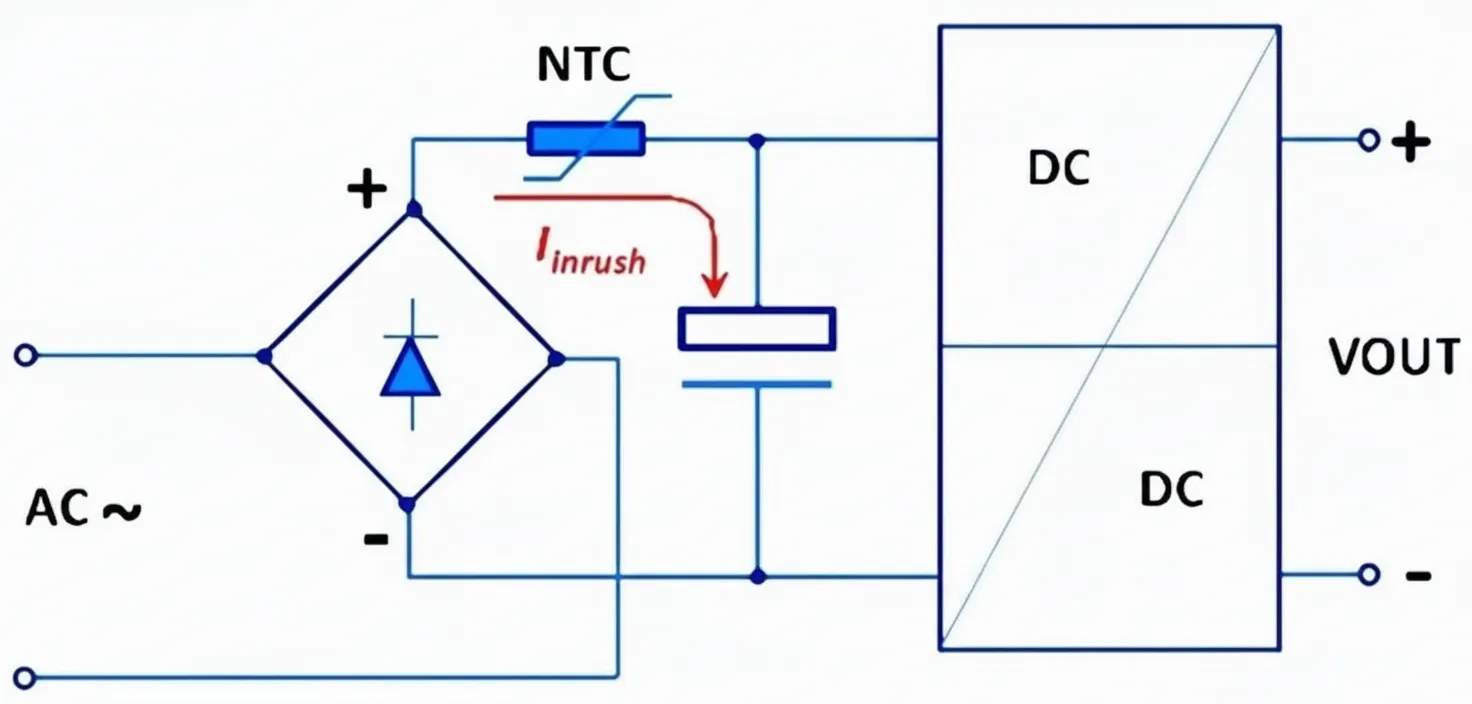
Typical SMPS input sequence: the AC input is first filtered, then rectified by a bridge into DC, smoothed by a large electrolytic capacitor, and finally presented to the DC-DC converter stage. The input inrush occurs when the electrolytic capacitor is charged for the first time. Its magnitude depends on the instantaneous mains voltage at turn-on and the total loop resistance formed by the rectifier and capacitor. If turn-on coincides with a mains voltage peak, the inrush current reaches its maximum.
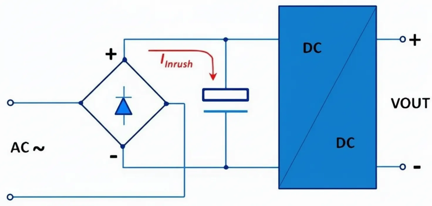
SMPS start-up inrush current illustration
Six methods to limit inrush current
1. Series NTC thermistor
Placing a negative temperature coefficient (NTC) thermistor in series with the input is the simplest method to limit inrush current. At start-up the NTC is at ambient temperature and has relatively high resistance, which limits current. After the supply runs, the NTC self-heats and its resistance drops significantly, typically to about one-fifteenth of the cold value, reducing steady-state power loss.
Choosing an NTC with an appropriate resistance-temperature characteristic minimizes power loss during normal operation.
Advantages:
- Simple and low cost.
Disadvantages:
- NTC limiting is sensitive to ambient temperature. At low ambient temperature the cold resistance can be so high that the charging current is too small and the SMPS may fail to start. At high ambient temperature the cold resistance may be too low to provide effective inrush limiting.
- After a brief power interruption the NTC may remain hot and its resistance low, so immediate restart will not be limited effectively.
- NTC dissipation reduces overall conversion efficiency.
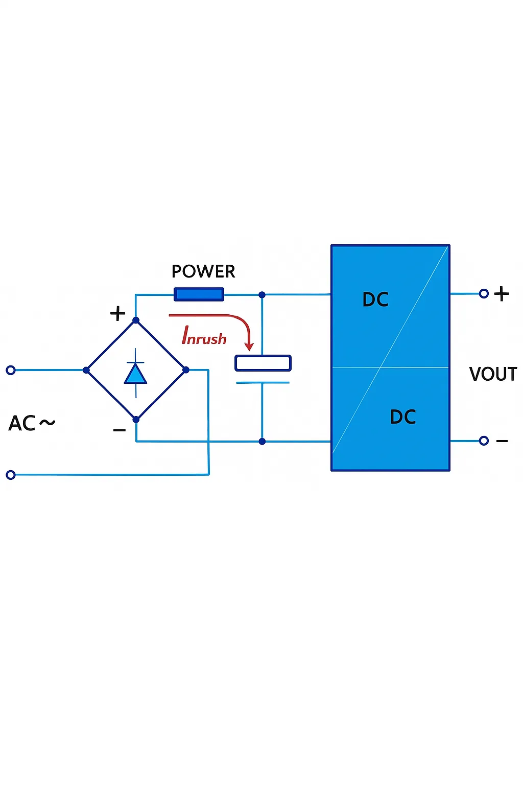
2. Series power resistor
For low-power SMPS designs, a fixed power resistor in series can limit inrush current. This method is not energy efficient because the resistor dissipates power both during startup and in steady state.
Advantages:
- Simple circuit, low cost, and inrush limiting is largely unaffected by ambient temperature.
Disadvantages:
- Suitable only for low-power SMPS.
- Significant negative impact on conversion efficiency.
3. Series resistor during start, then bypass it
For supplies rated several watts or higher, keeping a series resistor permanently in the input is inefficient. The resistor is only needed during startup and should be bypassed immediately afterward. Typical implementations parallel the power resistor with a relay, an NTC, or a MOSFET so the resistor limits current on startup and is removed from the circuit afterward.
Example implementations include paralleling the power resistor with an NTC, or bypassing the resistor with a relay once the supply starts.
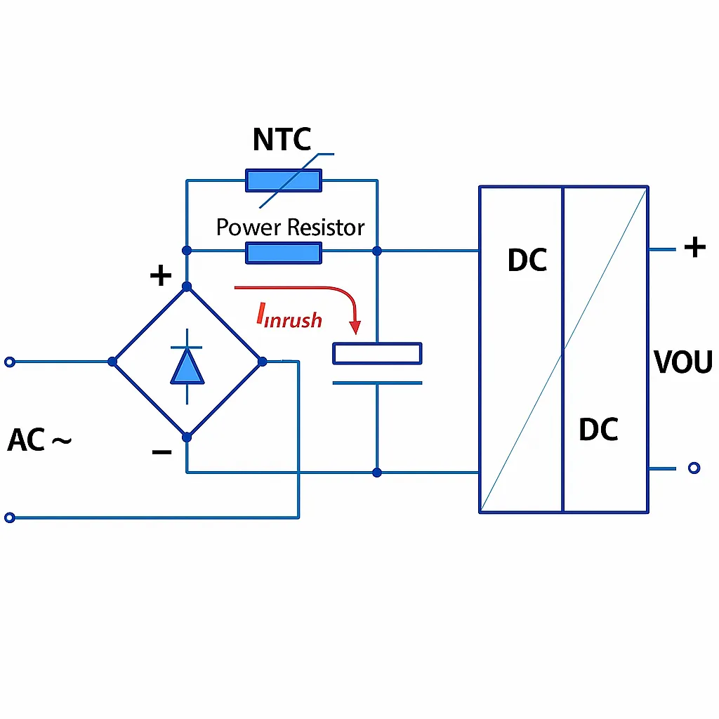
When starting at ambient temperature, the combined resistance of the power resistor and NTC is high enough to limit inrush. During low-temperature starts the NTC remains high resistance, maintaining effective limiting. As the NTC heats, its resistance drops and the NTC shunts the power resistor.
Advantages:
- Simple and effective across a range of ambient temperatures.
Disadvantages:
- Greater impact on efficiency compared with bypass-free solutions.
- Higher inrush at elevated ambient temperatures.
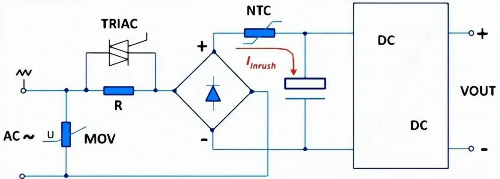
4. Series resistor with an SCR bypass
A fixed series resistor combined with an SCR (silicon controlled rectifier) can limit input inrush. At turn-on the SCR is off and current flows through the resistor to limit inrush. Once the conditions to fire the SCR are met, the SCR conducts and effectively bypasses the resistor, greatly reducing steady-state power loss.
Advantages:
- Low steady-state power loss.
- Inrush limiting is largely temperature-insensitive.
Disadvantages:
- Larger size and higher cost compared with simpler methods.
5. MOSFET switch with delay network
The basic idea is to insert a MOSFET in series with the DC input so that, at turn-on, the MOSFET gradually conducts to limit the inrush into the input filter capacitors. A delay network made from two resistors, one capacitor, and a Zener diode controls the MOSFET gate drive so the MOSFET ramps on smoothly. As the circuit reaches steady state the MOSFET is fully on.
Adjusting the filter capacitor values and delay network parameters allows tuning of the inrush suppression behavior for a specific product design.
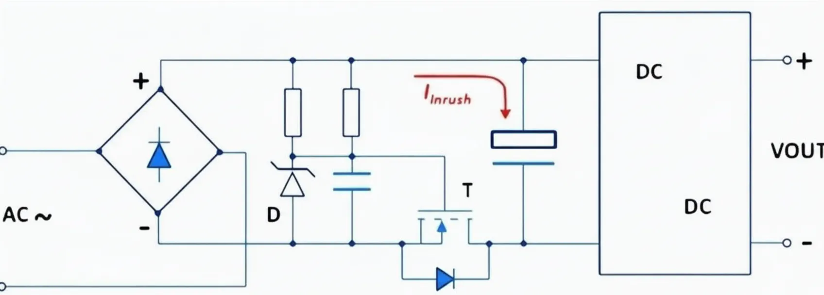
Using a controlled MOSFET switch provides effective inrush suppression while minimizing steady-state losses.
6. PTC thermistor
In some cases a positive temperature coefficient (PTC) thermistor is the preferred inrush limiter. When ambient temperature is high, an NTC may have too low a cold resistance, reducing its ability to limit inrush. A PTC exhibits higher resistance at elevated temperature and can perform better in that scenario.
At very low ambient temperatures an NTC may have such high resistance that the supply current is below the minimum needed for startup; a PTC can be preferable in those cases. For systems that cycle frequently, multiple inrush events occur with little time between them. An NTC may not have time to cool down and will remain at low resistance, increasing the risk of excessive inrush on subsequent starts. In short-circuit events an NTC can heat rapidly and, while hot, allow increased current that accelerates damage. In these situations a PTC is often the better choice.
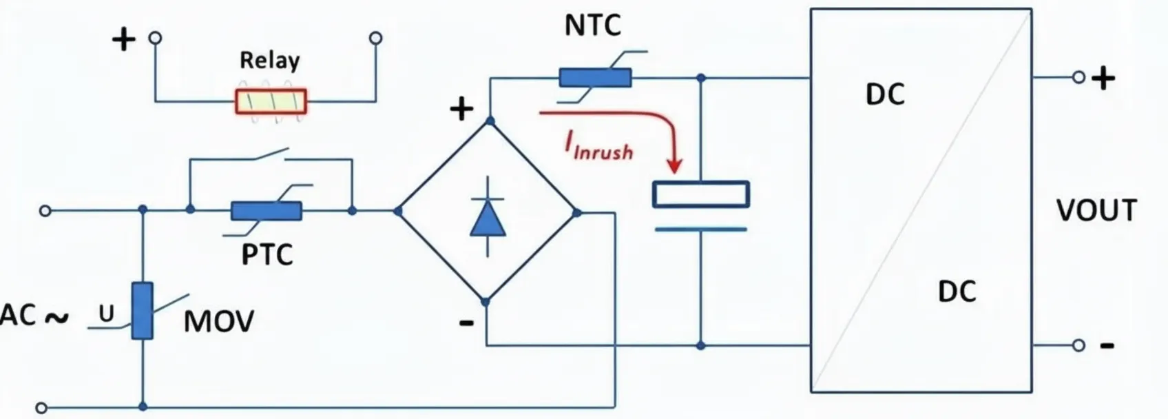
PTC thermistors typically cost more than NTCs and PTC-based circuits usually require a bypass mechanism so the PTC can be removed from the circuit once it heats. For example, a relay can bypass the PTC when the sensed current drops below a threshold. Despite higher cost, PTCs are used in applications such as DC motors and solenoids because of their inherent self-protection: their resistance increases when current becomes excessive.