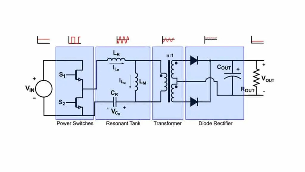
1. Common communication methods
Earlier articles on digital power and analog power discussed that digital power supplies need communication functions to support configuration and management. Using host PC software, engineers can set power parameters and control power states. Because the digital power control core outputs TTL-level signals, level translators are required when interfacing with external devices that use different signaling standards. Common communication interfaces in digital power supplies include RS485, RS232, CAN, TCP/IP, and I2C.
Communication method classification
Communication methods can be classified by data transfer style into serial and parallel communication.
Parallel communication transfers data in bytes or multiples of bytes. It has high throughput but is costly over long distances, so it is suitable for short-distance, high-volume, and high-speed exchanges.
Serial communication, also called point-to-point communication, transmits one bit at a time. It requires fewer lines, lowers cost, and is easy to extend, making it suitable for long-distance transmission. Serial communication is currently the most commonly used approach.
Serial communication can also be categorized as follows:
- By direction: simplex, half-duplex, and full-duplex.
- Simplex communication supports one-way transfer; sender and receiver roles are fixed.
- Half-duplex allows two-way transfer, but not simultaneously; sender and receiver roles can switch, as in a walkie-talkie.
- Full-duplex allows simultaneous bi-directional transfer, with transmitters and receivers at both ends and two data lines for signal transmission.
- By synchronization: synchronous and asynchronous communication.
- Synchronous communication requires matching clock frequencies at both ends; data frames include synchronization characters, data characters, and CRC.
- Asynchronous communication does not require clock synchronization; bytes are framed with start and stop bits so the receiver can correctly sample the data.
2. Communication circuits
RS-232
RS-232 uses inverted logic levels. A "0" level is in the +3 to +15 V range, while a "1" level is in the -15 to -3 V range. The 9-pin connector is the mainstream interface form.
RS-232 level translation circuits are available in isolated and non-isolated forms. Non-isolated implementations can use discrete transistors or non-isolated level translators such as MAX232 variants. Isolated level translators include RSM232, ADM3251, and similar isolated transceivers.
Below is a typical discrete transistor-based level translator and an RSM232 interface schematic.
Working principle of the transistor level translator:
- The diode D1 and capacitor C7 hold node A at approximately -3 V to -15 V.
- When TXD = 1, Q3 is off, so PCRXD and PCTXD are equal; PCRXD = 1.
- When TXD = 0, Q3 conducts, making PCRXD approximately +5 V; PCRXD = 0.
- When PCTXD = 1, Q4 is off, RXD is about +5 V; RXD = 1.
- When PCTXD = 0, Q4 conducts, RXD is 0; RXD = 0.
- D2 prevents reverse breakdown of Q4's BE junction.
RS-485
RS-485 addresses RS-232 limitations such as short range and low speed by using differential signaling, which provides strong noise immunity. RS-485 uses a twisted pair (A and B lines) for data transmission. When the voltage difference between A and B is -6 V to -2 V it indicates "0", and when the difference is +2 V to +6 V it indicates "1". Termination resistors matching the cable characteristic impedance should be connected at each end of the bus, as shown below.
RS-485 transceivers are available in isolated and non-isolated versions. Typical non-isolated chips include MAX3485 and SN75176 variants; common isolated parts include RSM3485, ISO3082, and similar isolated transceivers.
CAN
CAN bus uses differential signaling with lines CAN_H and CAN_L. A dominant state (logical "0") is represented by a differential voltage around 2 V (CAN_H ≈ 3.5 V, CAN_L ≈ 1.5 V). A recessive state (logical "1") has a differential voltage of 0 V (CAN_H ≈ 2.5 V, CAN_L ≈ 2.5 V). CAN employs data frames for message transfer; the standard CAN data frame structure is shown below.
CAN transceiver circuits may be isolated or non-isolated. Non-isolated designs connect the controller's CAN TX/RX directly to a driver IC without electrical isolation. For improved network stability and to protect against ground loops, CAN interfaces often use isolation. Isolation can be implemented with discrete optocouplers or integrated isolated CAN transceivers.
Common CAN transceiver ICs include TJA1050, MCP2551, and ISO1050.
For example, ISO1050 integrates electrical isolation and uses an isolation barrier between VCC1 and VCC2, often implemented with an isolated transformer. Decoupling capacitors are placed between the chip supply pins and ground to reduce interference. TVS diodes are typically placed between CAN_H/CAN_L and ground for surge protection.
TCP/IP
The TCP/IP protocol suite is structured into four layers: the link layer, the network layer, the transport layer, and the application layer. The application layer includes protocols such as HTTP and FTP; the transport layer includes TCP and UDP; the network layer carries IP addressing; the data link layer adds Ethernet framing and CRC for transmission.
TCP/IP communication can be implemented with embedded TCP/IP Ethernet stack chips (for example, W5500, CH395) or via a network switch. In many digital power supply applications, the latter approach is commonly used.
Summary
This article introduced the principles and circuit implementations of the communication methods commonly used in digital power supplies, including RS-232, RS-485, CAN, and TCP/IP. With sampling circuits, driver circuits, and communication circuits covered, the peripheral circuit section is complete. The next article will address common power supply topologies, starting with the phase-shifted full-bridge topology and its operating principle.