Overview
Can a charger be life-threatening? Faults such as transformer leakage inside a mobile phone charger can allow mains AC (for example, 220 VAC) to leak to the DC output and be conducted through a data cable to the phone's metal enclosure, potentially causing fatal electric shock.
Why can a phone charger output contain mains AC? What factors matter when selecting an isolated supply? How do you distinguish isolated from non-isolated power supplies? The industry commonly describes them as follows.
Definitions
Isolated power supply: There is no direct electrical connection between the input and output circuits. The input and output are insulated and present a high-resistance state with no direct current path between them, as shown in Figure 1.
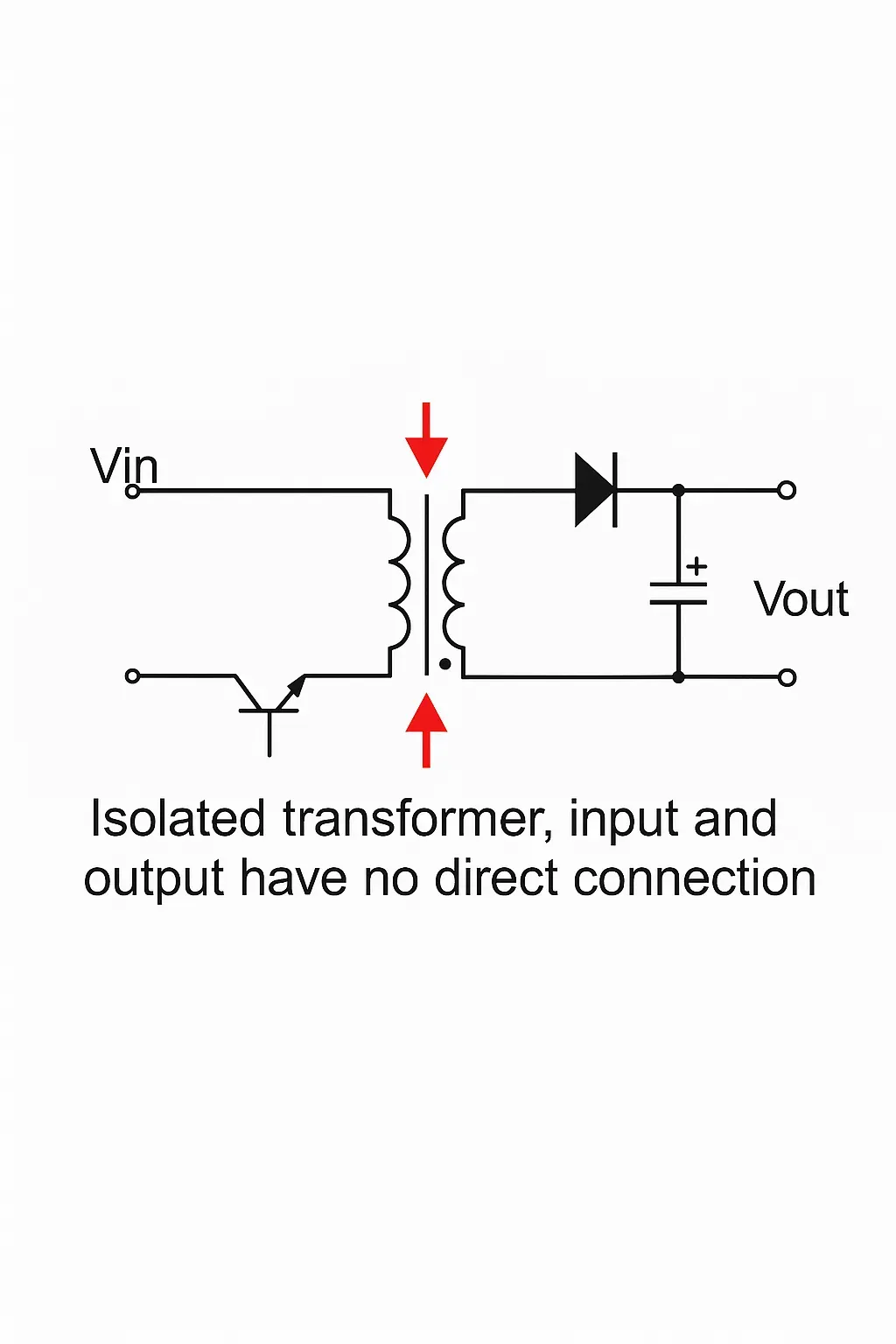
Figure 1 Transformer-based isolated power supply
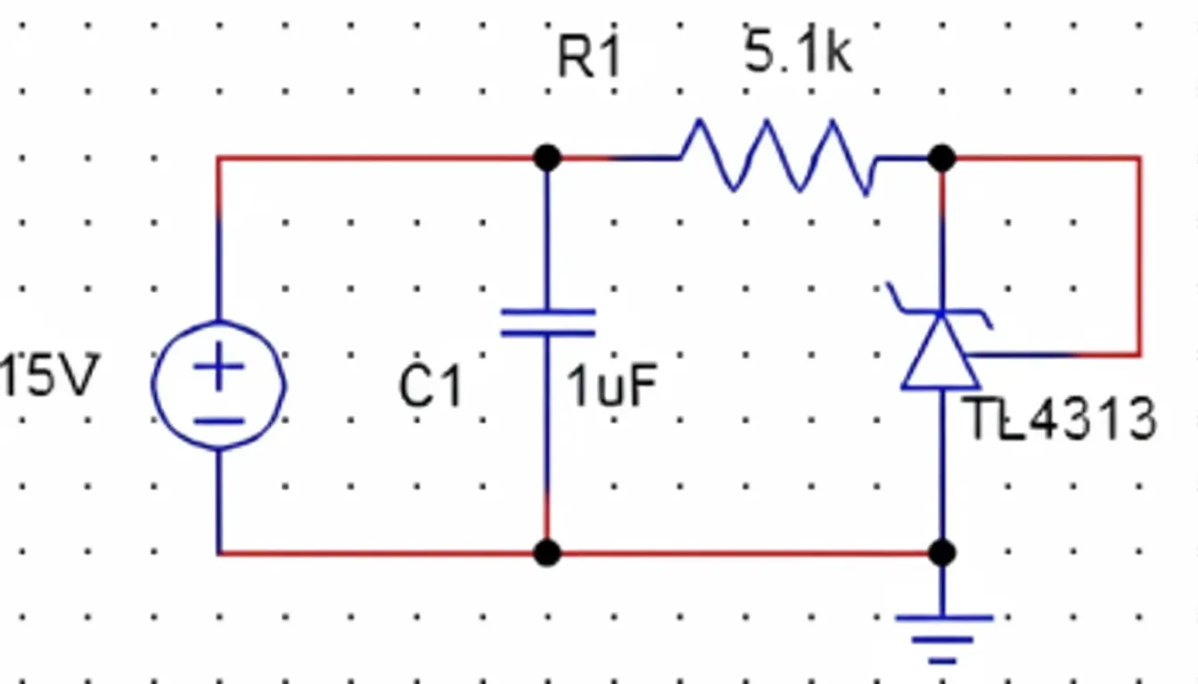
Non-isolated power supply: There is a direct current path between input and output, for example a common ground between input and output. Examples: isolated flyback topologies versus non-isolated buck converters, illustrated in Figure 2.
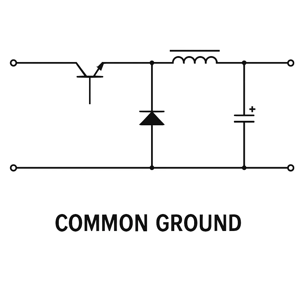
Figure 2 Non-isolated power supply
01. Advantages and Disadvantages
Based on the definitions above, common non-isolated topologies include Buck, Boost, and Buck-Boost. Common isolated topologies use isolation transformers and include flyback, forward, half-bridge, and LLC. Intuitively, isolated and non-isolated supplies have complementary strengths and weaknesses.
Key differences:
- Isolated modules generally offer higher safety isolation and reliability, but at higher cost and slightly lower efficiency.
- Non-isolated modules have simpler structure, lower cost, higher efficiency, but lower inherent safety isolation.
Typical cases where isolated supplies are recommended:
- Applications involving possible electric shock, e.g., mains-derived AC-DC supplies that must isolate the user from mains.
- Systems interconnected by serial communication buses such as RS-232, RS-485, or field networks like CAN, where physically separated systems each have their own supplies and electrical isolation is used to protect against transient high-voltage events and to reduce signal distortion by breaking ground loops.
- External I/O ports where isolation improves overall system robustness and reliability.
02. How to Choose Between Isolated and Non-Isolated
Selecting between isolated and non-isolated supplies depends on application requirements. Typical recommendations for embedded power distribution:
- Use isolated supplies for system front-ends to improve immunity to interference and ensure reliability.
- For on-board ICs or local circuit rails where cost and board area matter, non-isolated solutions are often preferred.
- Where safety is required, such as mains-connected AC-DC supplies or medical equipment, isolation is mandatory; in some cases reinforced isolation is required.
- For remote industrial communication nodes, isolated supplies for each node reduce ground potential differences and coupling interference.
- For battery-powered designs with strict energy constraints, non-isolated supplies are often favored for higher efficiency.
Examples of module choices are sometimes given, such as isolated AC-DC modules for low-power applications and buck-type non-isolated AC-DC modules for compact, efficient solutions in the 1–5 W range.
03. Isolation Module Selection Considerations
Isolation withstand voltage is a key module specification. The GB 4943 safety standard (China's information technology equipment safety standard) defines tests and requirements intended to prevent electrical hazards such as electric shock, physical injury, or explosion. The following diagram shows a typical isolated power structure.
As an important module parameter, the standard also specifies test methods for isolation withstand voltage. A simple test uses equipotential connections as shown below.
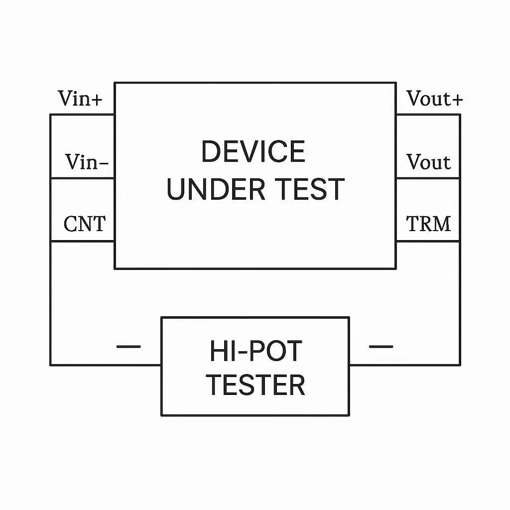
Test method summary:
- Set the hipot tester voltage to the specified withstand value, current limit to the specified leakage current, and the timer to the required test duration.
- Start the test and apply voltage. During the specified time the module must show no breakdown or arc.
- When testing, select appropriate soldering temperatures and avoid repeated rework that could damage the module.
Other considerations:
- Confirm whether the module is AC-DC or DC-DC.
- Verify the isolation rating, e.g., whether 1000 VDC isolation meets the insulation requirements for the application.
- Check for comprehensive reliability testing: performance, tolerance, transient conditions, EMC testing, high/low temperature, extreme condition tests, lifetime tests, and safety approvals.
- Assess the module manufacturer's production process and certifications such as ISO 9001, ISO 14001, and OHSAS 18001.
- Confirm previous applications of the module in industrial, automotive, or other harsh environments if relevant to your design.
Industry practice commonly aims for isolation voltages of 1500 VDC and above for robust leakage and EMC performance, where the application requires it.
04. Practical Insights on Isolated vs Non-Isolated Supplies
A common misconception is that non-isolated supplies are inherently inferior because isolated units are more expensive. That view reflects older implementations. Non-isolated designs have matured considerably and can meet many safety standards with appropriate structural changes.
In practice, many failures in non-isolated supplies are caused by surge voltages on the AC input lines, for example lightning-induced surges or load-switch transients that momentarily reach several kilovolts. These surges can penetrate into non-isolated buck circuits and damage constant-current sense circuits or controller ICs, producing destructive faults. Isolated flyback supplies can also suffer MOSFET or controller failures under extreme surges.
In LED driver and small switch-mode adapter applications, a large fraction of field failures are due to surge-induced damage. LED loads are particularly sensitive to surges. Because non-isolated circuits often expose the load to a portion of the input surge directly, their surge suppression requirements are stricter.
Component count alone does not determine real-world reliability. While non-isolated circuits typically use fewer components, the key issue is surge immunity and suppression capability. Isolated supplies inherently provide some surge attenuation because energy must pass through a transformer, but non-isolated solutions can be made robust with adequate surge protection measures.
Advantages of non-isolated supplies are higher efficiency and lower cost. Typical suitable use cases for non-isolated supplies:
- Indoor fixtures where the electrical environment is controlled and surge exposure is limited.
- Applications using high voltage and low current; for low-voltage, high-current situations the benefits of non-isolated designs are less pronounced.
- Environments with relatively stable input voltage where surge exposure is low.
Where surge protection is adequate, the applicability of non-isolated supplies expands significantly. Conversely, isolated supplies are still vulnerable to surges; designers should include surge-consideration in the design and advise users to avoid surge conditions when possible.
05. Conclusion
This article introduced the differences between isolated and non-isolated power supplies, summarized their advantages and disadvantages, outlined typical application scenarios, and described key considerations when selecting isolated modules. Use these points as a technical reference when designing products and when diagnosing power-related faults.