What is PSRR
PSRR (power supply rejection ratio) measures how well a circuit suppresses ripple on its input power. It is defined as the logarithmic ratio of output ripple to input ripple, expressed in decibels (dB). The formula is shown in the image below.
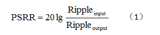
In the formula:

: peak-to-peak ripple in the input voltage

: peak-to-peak ripple in the output voltage
PSRR increases as output ripple decreases for the same input ripple. Applications with strict ripple requirements—such as RF, wireless systems, and sophisticated New energy vehicle electronics—typically require LDOs with high PSRR. The following sections summarize various methods to measure LDO PSRR.
PSRR Measurement Principle
Superimpose an AC voltage Vin_AC of known frequency and peak-to-peak amplitude Rippleinput onto the DC input voltage Vin_DC of the LDO (the AC amplitude is typically hundreds of millivolts). Measure the peak-to-peak amplitude Rippleoutput of the AC component Vout_AC on the LDO output Vout_DC. Use the formula above to compute PSRR at that frequency.
The LDO input voltage during the test must satisfy:
- The maximum input voltage must not exceed the LDO maximum operating voltage.
- The minimum input voltage must be greater than the LDO output voltage plus dropout.
Although the PSRR measurement principle is straightforward, practical measurement raises two main challenges:
- How to superimpose an AC voltage on a DC input? Signal generators with DC offset appear suitable, but they typically supply only tens of milliamps and cannot drive LDOs with larger input current requirements.
- How to measure the peak-to-peak AC component on the LDO output? General-purpose oscilloscopes can measure down to the millivolt level; when the LDO PSRR is around 60 dB, the output ripple is often below 1 mV, which an oscilloscope cannot measure accurately.
The following sections describe solutions to both issues.
Superimposing AC on DC Input
1. Input injection unit
Use a dedicated input injection unit, for example J2120A, with bandwidth from 10 Hz to 10 MHz, maximum DC voltage up to 50 V, and output current up to 5 A. Use a network analyzer to measure the AC components at the LDO input and output and generate the PSRR plot over the desired frequency range.
2. Summing amplifier
Use an operational amplifier to build a summing circuit that combines the DC voltage and the AC signal at its output. The op amp must meet these conditions:
- Bandwidth covering the LDO test frequency range.
- Maximum output current at least equal to the LDO input current requirement.
- Output voltage range covering the LDO input voltage range.
Examples of op amps that meet these requirements include OPA552, OPA564, and THS3120. The low cutoff frequency is set by C1 and R1; the high cutoff is limited by the op amp bandwidth.
If a signal generator with sufficient DC offset is available, the op amp can be configured as a voltage follower. When using this method, remove the LDO input capacitor to avoid instability of the op amp.
3. LC node method
Use an inductor and capacitor to combine DC and AC voltages. The highest usable frequency is set by L1 and C1, while the lowest frequency is determined by C1.
Measuring LDO Output AC Voltage
1. Oscilloscope measurement
Typical oscilloscopes can measure millivolt-level signals. When LDO PSRR is not higher than 40–50 dB and the input AC amplitude is 1 Vpp, the output AC amplitude at the same frequency will be about 3–10 mVpp, which an oscilloscope can measure directly.
2. Amplifier plus oscilloscope
When LDO PSRR exceeds 50 dB, the output ripple is often below 1 mV and cannot be measured directly with an oscilloscope. An amplifier can boost the LDO output AC by 100x or more before measurement. Design considerations for the amplifier include:
- The amplifier input will see the LDO DC output; a coupling network is needed to remove DC.
- The amplifier's self-noise must be much lower than the amplified AC signal.
- Input offset voltage must be small, otherwise the offset will be amplified into a large DC output.
- The amplifier bandwidth must cover the PSRR measurement frequency range.
Choose low-noise, low-offset, high-bandwidth op amps such as OPA211, OPA228, or OPA189. The low cutoff frequency is set by C1 and R1, and the high cutoff by the op amp bandwidth.
Related Reading: Doherty Amplifier Basics and Theory
3. Spectrum analyzer measurement
Spectrum analyzers can measure microvolt-level signals and can be used with high-impedance input probes to measure the LDO output AC. High-impedance high-quality probes are expensive and may not be available in all labs. As an alternative, build a high-input-impedance probe using an op amp, as described by Steve Hageman for extending RF spectrum analyzer usability. A suitable op amp for this probe is OPA656.
Example Measurement
The LDO measured here is TPS7A4901. The TPS7A4901EVM output was redesigned to 1.2 V and the output capacitor changed to 10 uF. THS3120 was used to sum the DC and AC voltages; the THS3120EVM was modified to the circuit. OPA211 was used to build the 100x amplifier.
THS3120 and OPA211 were powered from ±15 V. The THS3120 DC level was 3.2 V and the AC sine input was 1 kHz at 1 Vpp. The TPS7A4901 delivered 150 mA output, with NR/SS and feedforward capacitors not connected. Figure 8 shows the amplified output ripple (yellow) and input ripple (blue). Figure 9 shows the FFT of the amplified TPS7A4901 output ripple.
It comes out that the output ripple amplitude at 1 kHz is -26.46 dBV. Converted back to the unamplified LDO output, the 1 kHz ripple is 0.95 mVpp. Using the formula above yields a PSRR of 60.4 dB, which is close to the 62 dB value listed in the datasheet. By changing the input AC frequency, PSRR can be measured across different frequencies.
If an input injection unit and network analyzer are available, they provide a convenient way to obtain the PSRR curve over a frequency range. Without those instruments, use one of the input summing methods combined with one of the output measurement methods described above. Measure input and output AC amplitudes at a given frequency, calculate PSRR using the formula, then repeat at other frequencies to build the PSRR curve.