Background
An engineer designing a circuit schematic may use a microcontroller that is typically powered at either 5V or 3.3V. For example, in an air purifier design the microcontroller might run at 5V, so its I/O pins operate at 5V levels. If the design also uses a PM2.5 sensor that runs at 3.3V, its I2C signals will be 3.3V.
The question then becomes: how can a 5V microcontroller communicate over I2C with a 3.3V PM2.5 sensor?
Two options
Option 1 is to change the microcontroller supply to 3.3V so both devices share the same supply voltage, avoiding level mismatch.
Option 2 is to implement a level-shifting circuit that converts between 5V and 3.3V logic levels.
If the microcontroller supply cannot be changed to 3.3V, a level-shifting circuit is the remaining approach.
Simple bidirectional MOSFET-based level shifter
There are many methods. One straightforward and reliable approach uses a single MOSFET and pull-up resistors to provide bidirectional level shifting, which is particularly suitable for I2C SDA signals.
Detailed circuit diagram:
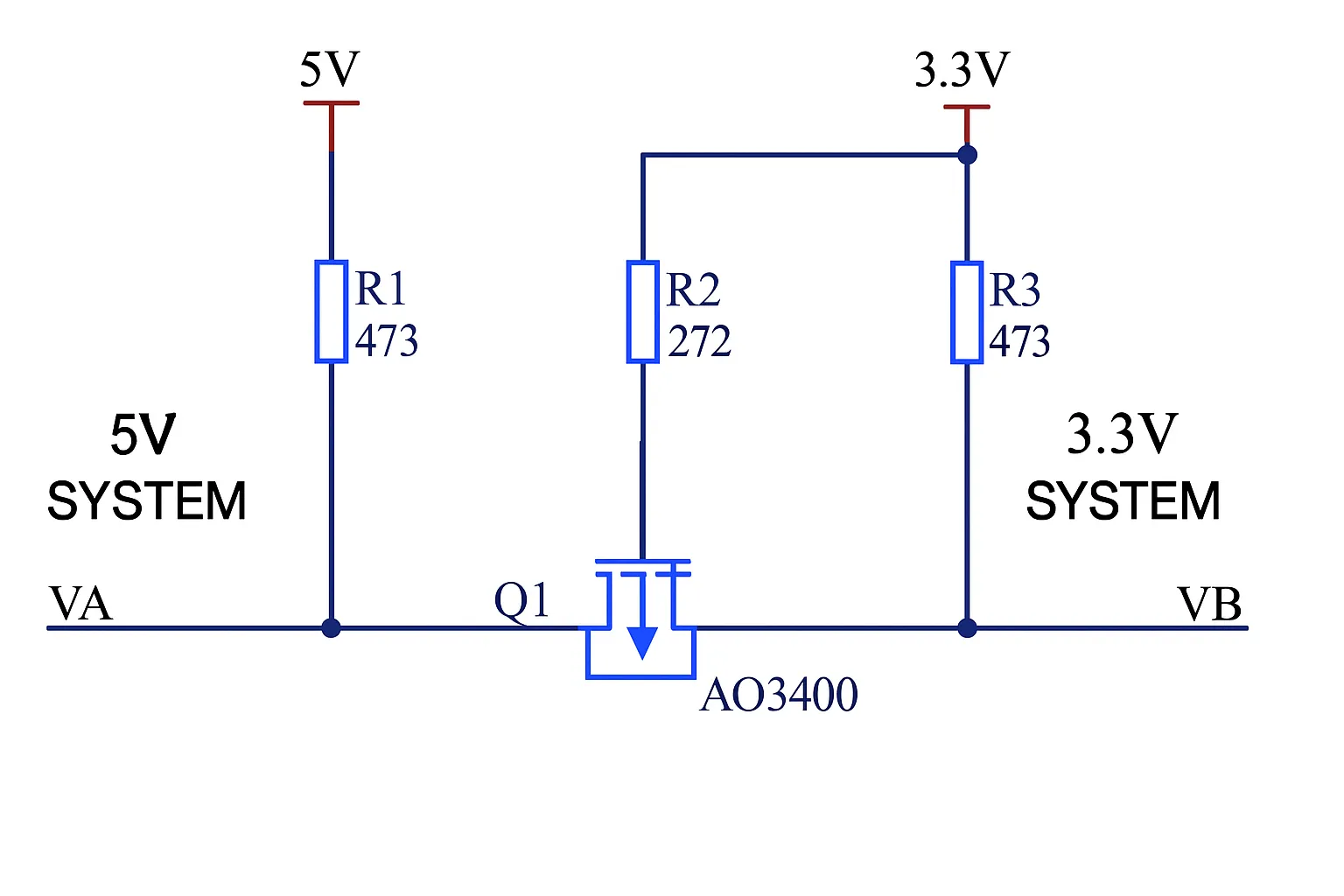
In this circuit, the left side is the 5V microcontroller system and the right side is the 3.3V sensor system. For I2C communication, SCL is a clock signal from the microcontroller to the sensor (left to right). SDA is a bidirectional data signal exchanged between the microcontroller and the sensor.
How it works: 5V to 3.3V
When the 5V microcontroller (VA) drives a 5V high, the MOSFET Q1 sees its gate and source at the lower-voltage side reference (3.3V), so the voltage at VB is limited to a 3.3V high level. This achieves conversion from 5V down to 3.3V.
If the microcontroller drives a 0V low, a diode in parallel in the circuit conducts: its anode is tied to a 3.3V pull-up resistor and its cathode is driven by VA at 0V, so the diode conducts. When the diode conducts, VB is pulled down from 3.3V to approximately 0.7V, yielding a low level. Thus, whether VA drives 5V high or 0V low, VB will present a 3.3V high or an approximately 0V low respectively.
How it works: 3.3V to 5V
Now consider the reverse direction: VB on the 3.3V side driving the 5V side VA.
If VB outputs a 3.3V high, Q1's gate and source are at the same potential (3.3V), so Q1 remains off. VA then appears as pulled up by R1 to 5V, effectively translating the 3.3V-side high into a valid 5V-side high.
If VB outputs 0V low, Q1's gate is at 3.3V while its source is pulled to 0V, turning Q1 on. This pulls VA down to 0V, so the 0V from the 3.3V side is translated to a 0V low on the 5V side.
Summary
This circuit provides bidirectional level shifting suitable for I2C signals using only one MOSFET and three pull-up resistors. It converts 5V to 3.3V and 3.3V to 5V reliably in both signal directions, making it a simple solution for mixed-voltage I2C interfaces.