1. Purpose of the protective earth (PE)
The primary purpose of the protective earth is to provide a reliable path to ground when an appliance develops a fault. If an insulation breakdown or component failure causes the appliance enclosure to become live, connecting the enclosure to earth allows protective devices to operate and reduces the risk of electric shock.
Types and uses of “ground” or reference points in electronics:
- Signal ground: also called reference ground; the common reference point for circuit signals and the return path for signal currents. Symbol: ⊥.
- DC ground: reference point for DC circuits, zero-voltage reference.
- AC ground: the neutral conductor of an AC distribution system; should be distinguished from protective earth.
- Power ground: reference point for high-current network devices and power amplifiers.
- Analog ground: zero-voltage reference for amplifiers, sample-and-hold circuits, A/D converters, and comparators.
- Digital ground: also called logic ground; zero-voltage reference for digital circuits.
- “Live ground” (hot referenced ground): in some switch-mode power supplies without an isolation transformer, the circuit “ground” is referenced to the mains and can be live. Symbol: (special hot-ground symbol).
- “Isolated ground” (cold ground): when an SMPS uses an isolation transformer or optocouplers in feedback, the output ground is isolated from mains and is not live. Symbol: ⊥.
Other protective and system grounds:
- Protective earth: installed to protect personnel; one end of the protective earth conductor is connected to the appliance, the other to the actual earth.
- Audio grounds: chassis shield grounding and dedicated audio ground connections are used to reduce interference in audio systems. Shielding should be connected to the appropriate audio ground point, often a separate buried earth for professional installations, and coordinated with isolation transformers and regulated supplies.
Ground handling and best practices
- Separate digital and analog grounds: In high-performance designs, digital and analog grounds should be separated and connected at a single point in the system.
- Floating versus earthed systems: A floating system isolates device grounds from earth, which can provide some immunity to interference but requires high insulation resistance (typically >50 MΩ). If insulation degrades, interference can increase. A common approach is floating circuit grounds with a chassis that is earthed for improved immunity and safety.
- Single-point grounding: Recommended for low-frequency circuits (generally below 1 MHz) to avoid ground loops.
- Multiple-point grounding: Recommended for high-frequency circuits (generally above 10 MHz) where parasitic capacitance and inductance are significant.
Common ground types in control systems:
- Digital ground (logic ground) for switching/digital signals.
- Analog ground for analog signal references.
- Signal ground, often used for sensor returns.
- AC supply ground, which can be a major source of noise.
- DC supply ground.
- Shield/chassis ground for preventing electrostatic and magnetic coupling.
General recommendations:
- Design and install grounding systems according to the function and purpose of each ground. Do not arbitrarily tie different ground types together; instead, group them into subsystems that each have a common grounding point or bus, and then implement a single overall ground connection where needed.
2. Differences between neutral (N) and protective earth (PE)
In typical wiring, an electrician uses a voltage tester to distinguish live and neutral conductors. If only one conductor causes the neon tester to light, that conductor is the live (hot) conductor. If both light, the neutral may be open.
Key differences:
- Neutral and protective earth are different concepts and must never be swapped or mixed.
- The protective earth is connected to local earth and has a near-zero potential relative to earth at the nearest grounding point.
- The neutral conductor is not guaranteed to be at earth potential locally; it is grounded at the distribution transformer or substation and may have a potential difference relative to local earth.
- Neutral can become live under certain fault conditions. For example, if the neutral conductor is open upstream, the neutral conductor near a device can be at mains potential and can cause electric shock.
How to identify neutral, earth, and live conductors
- Color codes (common conventions): live (L) often uses red, yellow, green, brown or other phase colors; neutral (N) uses black or blue; protective earth (PE) uses yellow/green bi-color.
- Using an RCD and a lamp: Install a residual-current device (RCD). Connect a lamp between the suspect conductor and a known live conductor; if the RCD trips, the conductor is likely earth; otherwise it may be neutral. Exercise caution: testing can produce sparks; follow safe procedures.
- Household procedure: With mains power on, a neon tester lights on live wires. If you disconnect the main neutral at the distribution point and then switch on a lamp, conductors that now light the tester are neutral. The one that never lights is earth. This method requires caution and knowledge of mains wiring.
- Using a multimeter: Set the meter to an AC range (e.g., 500 V). Touch one probe to a known live conductor and the other to the suspect conductor: a high voltage reading identifies live; a lower but nonzero reading may indicate neutral; near-zero indicates earth. Measure resistance between neutral and earth: a reliable earth typically shows low resistance (subject to local code requirements).
Note: These methods rely on correct and stable wiring; always follow local electrical codes and use appropriate safety precautions.
Consequences of incorrect connections
- Swapping live and neutral generally does not affect many appliances functionally for AC systems, but it can create hazards during servicing because switches may leave the appliance enclosure or internal parts live.
- Mixing or swapping neutral and protective earth is dangerous. If the earth conductor is tied to the neutral improperly, an exposed metal enclosure can become live, creating an electrocution risk.
- Using a protective earth as a neutral (for example to avoid meter registration) is unsafe and unreliable: variations in grounding conditions, weather, or transformer configurations can cause unstable voltages and serious equipment damage.
3. Earth conductor color codes
Power distribution commonly uses three-phase, four-wire systems. The three phase conductors are called “phase” or “live” conductors. The three phase ends tied together form the neutral or “N”. When the phases are balanced, the neutral conductor carries little or no current and is often close to earth potential because it is grounded at the transformer.
Protective earth connects equipment enclosures reliably to earth to prevent electric shock. Typical color conventions:
- Three-phase phase conductors: red, yellow, blue (or other local conventions).
- Neutral: black or blue.
- Protective earth: yellow/green bi-color.
- Single-phase lighting: live may be yellow or brown, neutral blue, protective earth yellow/green.
Notes about plug pin order: For some three-pin plugs, the left pin is neutral, the right pin is live, and the top is earth (when the plug faces you). Markings: L for live, N for neutral, E for earth.
4. Types of grounding and functions
Different grounding methods are used depending on application:
- Safety grounding (protective earth): connects exposed conductive parts of equipment to earth to prevent hazardous potentials and to ensure protective devices operate if insulation fails.
- Lightning protection grounding: connects lightning rods and related conductors to earth to protect structures and equipment from lightning strikes.
- Functional/working ground: provides a stable reference potential for correct operation of circuits; examples include DC, AC, digital, and analog grounds. Improper working grounding can increase interference and degrade circuit performance.
- Signal ground: common reference for signal sources; because signals are small and susceptible to interference, signal ground requires careful treatment.
- Analog ground: return/reference for analog circuitry; improper grounding can introduce noise and instability.
- Digital ground: return/reference for digital circuitry; sharp edges and high-frequency switching require careful layout and grounding to limit EMI.
- Power ground: reference for power supplies, often the negative terminal; since power supplies feed many subsystems, power ground must be stable and isolated from sensitive grounds when required.
- Power-driver ground (power ground): heavy-current return for loads and power drivers. Because of high currents, power ground must be separated from low-level signal grounds to avoid disturbance.
Shielding and grounding should be used together for EMI control. Typical shielding approaches:
- Electrostatic shielding: metal enclosures surrounding a charged conductor induce charges that cancel interior fields; connecting the shield to earth removes external fields.
- Electromagnetic shielding: high-conductivity metal structures reduce RF coupling; connect to earth where appropriate.
- Magnetic shielding: high-permeability materials guide magnetic flux to close the magnetic circuit; connecting to earth is generally recommended.
Grounding facilities are commonly classified as working ground (for circuit reference) and protective ground (for safety). Protective earth electrodes should be driven sufficiently into the ground (commonly 1.2–1.5 m depending on local standards) to achieve acceptable resistance.
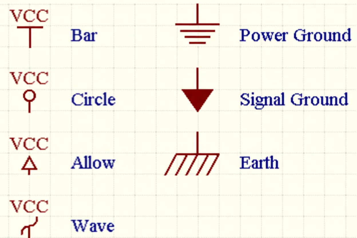
5. Ground symbols
Grounding is represented by several schematic symbols depending on purpose: signal ground, chassis ground, protective earth, and equal-potential bonding. Care is required when reading and drawing schematics to ensure the intended ground is clear.
- Signal ground: general reference for signal circuits.
- Chassis ground: the metal enclosure potential; often used as the signal reference where appropriate.
- Equipotential symbol: used to indicate points that share the same potential but are distinct from the main signal ground.
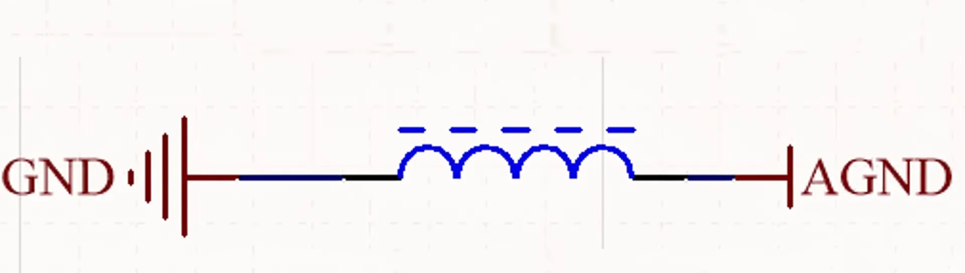
When analog and digital grounds coexist, it is common to separate AGND and DGND within the system and tie them together only at a single point on the power supply ground terminal to reduce interference. In schematics AGND and DGND are often shown with equipotential symbols to denote separate returns that share a single connection point.
6. How to connect protective earth
General steps for connecting protective earth:
- For three-pin sockets, wire the earth conductor to the dedicated earth terminal, neutral to the neutral terminal, and live to the live terminal. Connect equipment with conductive enclosures (e.g., washing machines, refrigerators) to earth.
- Create an earth electrode: drive a suitable conductor (steel pipe, angle iron, or dedicated earth rod) into the ground and connect the building earth conductor to it. Select electrode type and sizing based on soil resistivity and local regulations. Use sufficiently large conductors from the electrode to the distribution board and from there to individual outlets.
Earthing for household appliances helps dissipate leakage currents and static charge to earth. In power systems, temporary grounding during maintenance provides protection; standards often require a minimum cross-section for grounding conductors (for example, 25 mm2 bare copper for certain protective grounds).
High-voltage grounding equipment
High-voltage portable grounding kits are used during line and substation work to protect personnel and equipment. Typical components include an insulated operating rod, conductor clamps, shorting conductors, grounding conductors, and earth clamps. Kits are specified for different system voltages and are manufactured and tested to appropriate safety standards.
PC and workspace grounding
Chassis grounding reduces static on computer enclosures and can reduce certain types of interference. If building grounding is unavailable, a local earth rod or a dedicated earth connection can be used, but this is an inferior workaround compared to a proper building earth.
7. Why protective earth can become live
There are many causes for a protective earth conductor to be at a nonzero potential or to be live:
- Neutral and earth conductors are bonded or shared inappropriately.
- Neutral and earth conductors are wired incorrectly or reversed.
- Appliance leakage or internal fault causing phase-to-earth shorting.
- Different grounding points are at different potential (unequal earth potential), causing stray currents to flow in earth conductors.
- High-frequency interference or stray currents coupling into the protective earth conductor.
- Large currents flowing nearby causing induced or stray currents on the protective earth conductor.
Earth being at a dangerous potential has led to fatal accidents. For example, an investigation of a fatality involving an electric water heater found that the protective earth was energized due to a short between live and earth conductors in the meter box and poor earthing practices. Similar incidents have occurred in other cities; in many cases the appliances themselves passed individual product tests, but installation defects and earthing faults caused the protective earth to carry hazardous voltage.
Common causes in residential environments include overloaded circuits that overheat and damage insulation, poor-quality switches and sockets, ad hoc wiring, and lack of proper protective devices. Ordinary RCDs may not eliminate environmental earthing faults. Resolving such cases typically involves multiple parties (utility, manufacturer, developer), and identifying responsibility can be complex.
Mitigation and prevention measures include:
- Proper earthing at installation and correct wiring practices.
- Use of residual-current devices and appropriate protective devices on distribution boards.
- Routine inspection and maintenance of building wiring and meter installations.
- Good workmanship: insulating and securing all splices, correct routing of conductors, and avoiding shared or exposed connections.
Example case analysis: a streetlight transformer system had a phase conductor making metallic contact with a metal tower that was well earthed. Because the tower had a very low earth resistance relative to the transformer's neutral earth, the transformer's neutral and protective earth potentials became unbalanced and the system neutral (and connected equipment enclosures) rose to a hazardous voltage relative to local earth. The incident led to a fatality when a person completing a plumbing connection touched the energized grounding conductor while standing on a wet surface. The key lessons were the importance of preventing phase-to-ground contacts on distribution lines, installing RCD protection, and properly insulating and securing conductor joints.
8. Practical notes on earth/neutral/live wiring and symbols
Symbols and markings:
- Protective earth symbol: E (Earth).
- Live (hot) symbol: L (Live).
- Neutral symbol: N (Neutral).
Typical plug color coding (common conventions):
- IEC/European: green/yellow for earth, blue for neutral, brown for live.
- North America: green or green/yellow for earth, white or blue for neutral, black or brown for live.
Architecture of three-phase and single-phase supply:
- Three-phase distribution typically uses three phase conductors and a neutral conductor. The neutral is usually grounded at the transformer. In user installations a separate protective earth conductor is provided that is connected to a local earth electrode.
- Single-phase household supply usually has one live and one neutral conductor; many appliances require a dedicated protective earth connection for safety when the appliance has conductive parts.
Practical safety advice: never interchange L, N, and PE during wiring; follow the markings on sockets (L, N, and earth symbol) and local wiring regulations; ensure the protective earth is robustly connected and the earth electrode achieves acceptable resistance to earth.
9. Summary
Protective earth (PE) and neutral (N) serve different purposes: PE is a safety conductor tied to the local earth electrode to protect people from shock, while neutral is the return conductor for AC supply and is normally grounded at the distribution transformer. They must be treated separately in installations, and grounding practices should follow the intended function of each ground to ensure safety and electromagnetic compatibility. Proper wiring, appropriate protective devices, correct earthing electrodes, and careful design of signal and power grounds are essential for reliable and safe electrical systems.