Generation of power supply ripple
Common power supplies include linear power supplies and switching power supplies. Their DC output voltage is obtained from AC mains through rectification, filtering, and regulation. If filtering is incomplete, residual periodic and random components remain on top of the DC level, producing ripple. Under rated output voltage and current, the peak of the AC component in the DC output is usually referred to as the ripple voltage. Ripple is a complex disturbance that oscillates around the DC output; its period and amplitude vary with time, and ripple waveforms differ between supplies.
Effects of ripple
Ripple is generally harmful. Major impacts include:
- Ripple carried by the supply can generate harmonics and reduce overall efficiency.
- High ripple may produce surge voltages or currents, causing malfunction or accelerating aging of electrical equipment.
- In digital circuits, ripple can disturb logic relationships.
- Ripple introduces noise into communications, measurement, and metering instruments, degrading measurement accuracy and potentially damaging equipment.
When designing power supplies, ripple is usually reduced to a few percent or less; for sensitive equipment, even lower ripple levels are required.
Classification and standards for ripple measurement
Ripple measurement practices fall into two general categories: standalone power supply characterization and product-level debugging or measurement.
For supply characterization, testing is typically performed indoors at about 20°C, with relative humidity below 80%, minimal mechanical vibration and electromagnetic interference. Reference instruments and the device under test should be placed in the test environment for at least 24 hours before measurement.
For a pure power supply, ripple is measured under load. The applied load should draw at least 80% of the rated output current. For low-noise resistive or electronic loads, select the corresponding measurement standard. Different standards can yield different measurement results.
Ripple can be expressed as an absolute voltage or as a relative quantity. The ripple coefficient, an important metric for DC supply filtering performance, is calculated as the RMS value of the ripple voltage expressed as a percentage of the DC output voltage.
Measuring power supply ripple
Oscilloscopes are commonly used to measure supply ripple. Three typical probe methods are:
1) Ground-loop-minimized probe connection
Use a scope probe with a ground lead loop and place the probe tip directly on the positive output terminal while touching the ground loop directly to the negative output terminal. Keep the loop as short as possible; the measured peak reflects the ripple and noise on the output line.
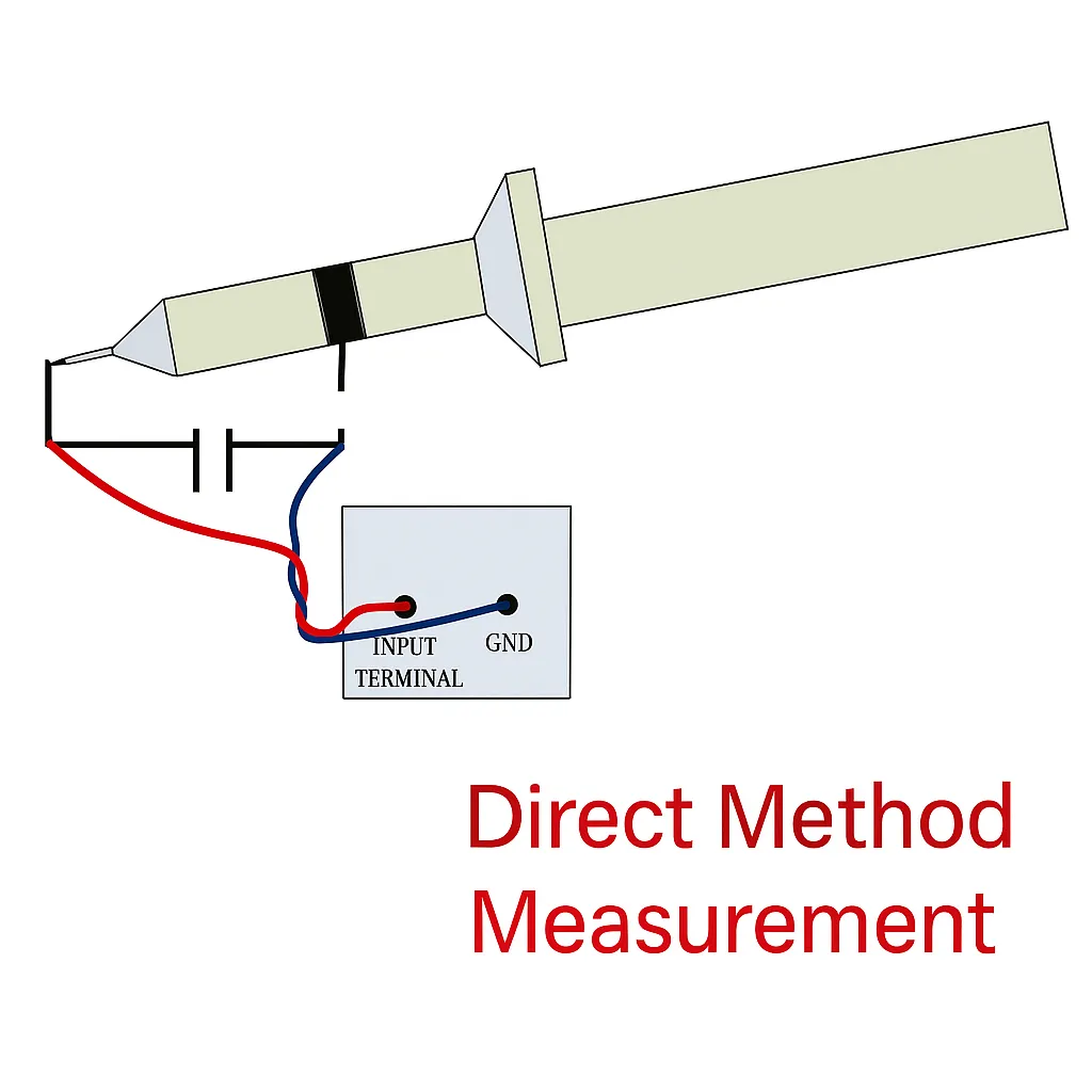
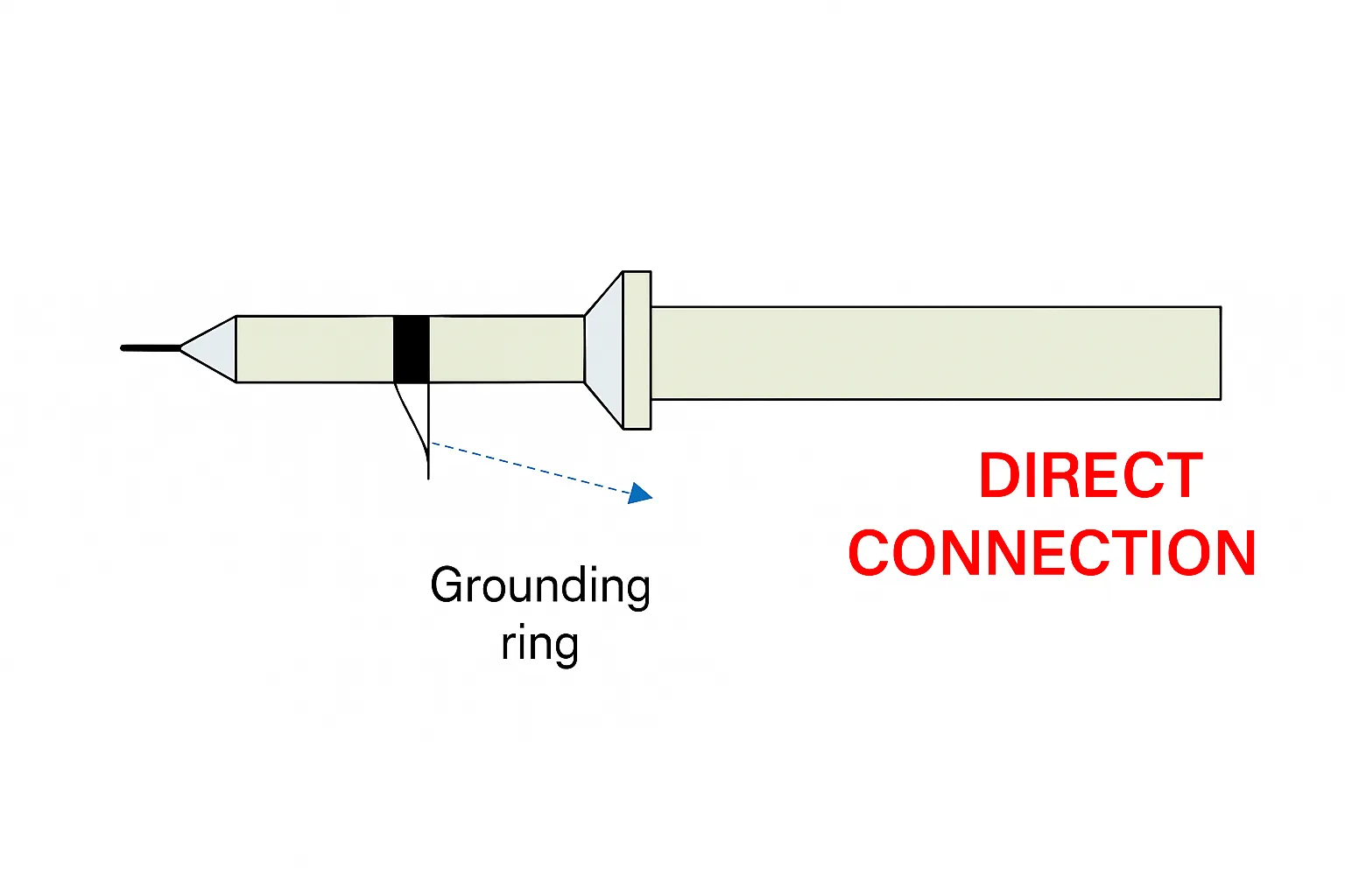
2) Direct grounding method
Connect the probe ground loop directly to the negative output terminal and use the probe tip for the output measurement point.
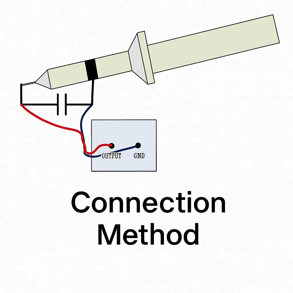
3) Twisted-pair with capacitor method
Connect the output terminals with twisted pair wiring to a capacitor, then measure across the capacitor with the oscilloscope.
When measuring ripple, be aware of the ripple bandwidth limit. Ripple is generally low-frequency noise, so select an oscilloscope whose bandwidth does not greatly exceed the ripple bandwidth. Enable the oscilloscope's bandwidth limit and set it to 20 MHz. Connect the probe shield to the output ground directly to minimize loop interference caused by long ground leads.
At the probe connection point, place a small ceramic capacitor in parallel with a small electrolytic capacitor to filter external interference and prevent it from entering the oscilloscope.
Methods for suppressing power supply ripple
Output ripple typically originates from five sources: low-frequency input ripple, high-frequency ripple, common-mode noise from parasitic elements, and ripple introduced by closed-loop regulation. Common suppression techniques include increasing filter capacitance, using LC filters, employing multi-stage filters, replacing switching supplies with linear supplies where feasible, and careful PCB/layout routing. Targeted measures based on the ripple type are usually more effective.
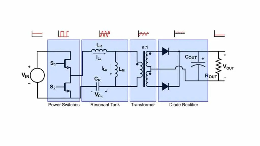
1. Suppressing high-frequency ripple
High-frequency ripple mainly originates from high-frequency power conversion circuits. When DC input is converted by high-frequency power devices and then rectified and filtered, ripple at the switching frequency is often present. The impact on the external circuit depends on the switching frequency and the structure and parameters of the output filter. Designing power converters to operate at higher switching frequencies can reduce the filtering burden for high-frequency ripple.
2. Suppressing low-frequency ripple
Low-frequency ripple magnitude is related to the size of filter capacitors in the output circuit. Capacitor values cannot be increased indefinitely, so some residual low-frequency ripple is unavoidable. After DC/DC conversion, residual AC ripple is attenuated but remains in the low-frequency range; its magnitude is determined by the control-loop gain and the DC/DC converter design. Both current-mode and voltage-mode controlled converters have limited intrinsic low-frequency ripple suppression and can exhibit significant low-frequency AC on the output. Therefore, low-frequency ripple must be addressed with additional filtering.
Measures include increasing the closed-loop gain of DC/DC converters, adding a pre-regulator stage, changing rectifier/filter capacitance, and adjusting feedback loop parameters to improve low-frequency ripple suppression.
3. Suppressing common-mode ripple
Common-mode ripple typically appears in switching supplies. When switching waveforms act on power devices, parasitic capacitances between devices, heat-sink/ chassis, and transformer windings, together with parasitic inductances in wiring, interact to generate common-mode noise. Suppression methods include:
- Reduce parasitic capacitance between control power devices, transformers, and chassis; add common-mode choke and capacitors at the output.
- Use EMI filters to effectively suppress common-mode ripple interference.
- Reduce the amplitude of switching spikes.
4. Suppressing control-loop induced ripple
Control-loop induced ripple often results from improper loop parameter settings. When the output fluctuates, the feedback network returns the fluctuation to the regulator loop, which can cause the regulator to respond in a self-excited manner and generate additional ripple.
Suppression strategies include preventing regulator self-excitation, selecting proper loop gain, ensuring regulator stability, and adding an LDO filter on the power output. Using an LDO filter at the output is one of the most effective methods to reduce ripple and noise.