Power factor is a coefficient that indicates the efficiency of electrical equipment. Its value depends on the nature of the circuit load. For purely resistive loads such as incandescent lamps and resistive heaters, the power factor is 1. Circuits with inductive loads typically have power factors less than 1.
A low power factor indicates a large reactive power component, which reduces equipment utilization and increases distribution losses. There is widespread discussion about power factor online, but some persistent misunderstandings can cause problems in system design. This article clarifies those concepts.
Origin and meaning of power factor
There are three basic types of loads in electrical systems: resistive, capacitive, and inductive. Resistors dissipate power, while capacitors and inductors store and release energy. For AC supply on a pure resistive load, voltage and current are in phase, i.e., the phase difference phi = 0 degrees.
For a pure capacitive load, current leads voltage by 90 degrees (phi = 90 degrees). For a pure inductive load, current lags voltage by 90 degrees (phi = -90 degrees). Power factor is defined as:
On a resistive load, active (real) power equals apparent power, so the power factor F = 1. On pure capacitive or inductive loads, the phase difference is 90 degrees, so F = cos(phi) = cos(90 degrees) = 0, and active power is zero.
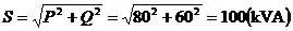
Thus, the load determines the magnitude and type of power drawn from a source. In other words, the source's output depends on the load, not the other way around. For example, when a UPS with a six-pulse rectifier front end has an input power factor of 0.8, if the UPS is asked to draw 100 kVA apparent power it must take 80 kW active power and 60 kvar reactive power from the preceding source. If the UPS input power factor were 0.6, it would require 60 kW active and 80 kvar reactive. The distribution between active and reactive power is determined by the load seen by the source.
Power factor characterizes the nature and magnitude of a load from the load input side; this is called the load input power factor. Once a load circuit is defined, its input power factor is fixed. For a UPS acting as a load to the mains or a generator, the UPS input power factor is determined by its front-end rectifier design and does not depend on the upstream source.
UPS output capability parameter — load power factor
1. The term "output power factor" is a misnomer
UPS units are manufactured with predefined ratings that include a rated load power factor, so that a range of units with different combinations of power and power factor can be offered as stock. When a UPS's rated load power factor matches the load's input power factor, the UPS can deliver its full rated power. If mismatched, the UPS must be derated.
Some people mistakenly call the UPS rated load power factor the UPS "output power factor." That error likely stems from thinking that since the UPS has an input power factor it must also have an output power factor. This confuses the single, unique electrical nature of a circuit seen from its input with a separate notion viewed from its output.
If a UPS had an actual output power factor in the sense often implied, a UPS rated at 100 kVA with an output power factor of 0.8 would be expected, under any load condition, to deliver 80 kW active and 60 kvar reactive power. In practice that does not occur. For example, a UPS rated 100 kVA at 0.8 load power factor can overload and transfer to bypass when driving certain linear loads. Also, if you measure the UPS output power factor with a power factor meter, you may see a reading of 1.0 with a linear resistive load and around 0.7 with an IT load that has diode-rectifier input filters. Those measurements are the load power factor, not an intrinsic UPS "output power factor."
Effectively, when you measure with a load connected you always measure the load power factor. Measuring an "output power factor" only makes sense with no load connected, but then both active and apparent output currents are zero even though voltages are present, so the ratio in the power factor definition is undefined. Therefore the notion of a practical, measurable UPS "output power factor" is not operational.
2. Factors that determine the rated load power factor
Why then does a 100 kVA UPS rated at 0.8 load power factor fail to deliver 80 kW with a linear load? In conventional low-frequency UPS designs, the inverter is sized for the rated active power, while reactive power is provided by an output capacitor C located after the inverter.
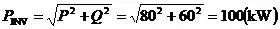
In the example of a 100 kVA UPS rated at 0.8 load power factor, the inverter is sized for 80 kW and the capacitor C is sized to provide 60 kvar of reactive power (plus any additional filtering capacitance required). When the UPS load power factor and the load input power factor are fully matched, the capacitor's reactive output QC cancels the load's inductive reactive requirement QL, since QC - QL = 0. The reactive loop current between C and the load inductance does not flow through the inverter, so the inverter only needs to supply the active current. Under matched conditions, the UPS can deliver 80 kW active and 60 kvar reactive to the load:
What happens if the load input power factor does not equal the UPS rated load power factor? Consider a linear load with input power factor = 1, a situation that often occurs during factory load tests. In this case the inductive component in the load is absent, so the output capacitor C can no longer supply reactive power to the load. The reactive current required by C for its 60 kvar is determined by its reactance XC:
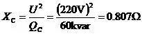
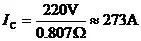
From this expression, the inverter output is effectively paralleled with a small reactive branch. To establish 220 V at the inverter output, the inverter must first supply the capacitor current IC, whose magnitude is:
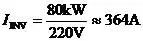
The inverter could originally supply a current IINV given by:
The inverter output current must first supply the capacitive current; the remainder is available to the load Ir, i.e.:
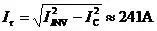
Therefore the load can only receive a reduced active power. In the example, the available load power Pr becomes approximately 53 kW:
Pr = 241 A × 220 V ≈ 53 kW
The same result can be derived from power equations:
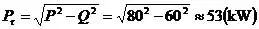
Thus, a 100 kVA UPS rated at 0.8 load power factor can only supply about 53 kW when driving a purely linear load. In general, if the load input power factor does not equal the UPS rated load power factor, the UPS must be derated. The specific derating depends on the UPS's designed load power factor.
3. Risks of misunderstanding UPS power factor
Mistaking the load power factor for a UPS "output power factor" not only misassigns responsibility but also creates a non-existent requirement. If regulators or standards writers adopt this misconception, the impact on UPS manufacturers can be significant.
For example, when high-power UPS units were first imported, testers noted that a 100 kVA UPS rated at 0.8 did not deliver 80 kW with a linear test load. Some assumed the manufacturers were at fault and pressed suppliers to increase inverter sizing so that the inverter itself would also cover the 60 kvar reactive component. That change would effectively add the reactive power into the inverter capacity, increasing inverter cost by around 20%. Drive and control circuitry would also require upgrades, further raising cost. If all manufacturers adopt that change, the industry-wide impact is large.
Even if boosting inverter size yields the 80 kW active output, doing so without adjusting the existing 60 kvar capacitor means the load power factor specification is no longer 0.8 under the original design assumptions. The apparent, active, and reactive power triangle changes, so the numerical power factor value becomes inconsistent with the original rating.
Such ad hoc changes are not justified scientifically and can harm manufacturers and users. Power factor is not a percentage in the naive sense. Active and reactive power are orthogonal components. Treating 80 kW as "80%" and 60 kvar as "60%" and then summing them to 140% is incorrect. The relationship among apparent power S, active power P, and reactive power Q follows the Pythagorean relation of a right triangle, so P and Q cannot be added linearly without considering their vector relationship.
Power factor and output voltage harmonic distortion are both important UPS performance metrics but they are distinct. Harmonic distortion addresses waveform quality and interference, while power factor characterizes the load type and real vs reactive power distribution. Both should be considered separately in design and testing.