Conventional Superheterodyne Receiver
The conventional superheterodyne radio receiver architecture has been used for nearly a century. The block diagram below reviews the analog receiver structure to provide a basis for comparison with digital receivers.
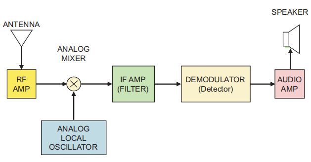
The RF signal from the antenna is amplified. Typically, an RF stage with a tuner amplifies signals only within the band of interest. That amplified RF is fed to a mixer. A local oscillator (LO) signal, whose frequency is set by the radio tuning control, is also applied to the mixer. The mixer converts the desired input signal to an intermediate frequency (IF), as shown.
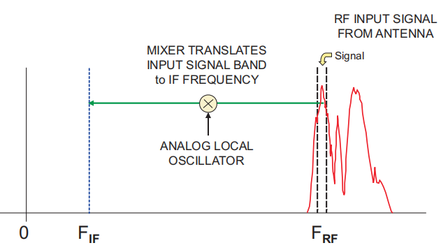
The IF stage is a bandpass amplifier that passes only one signal or station. Common center frequencies are 455 kHz and 10.7 MHz for commercial AM and FM broadcasting. A detector restores the original modulation from the IF output; for example, AM uses an envelope detector and FM uses a frequency discriminator. In a typical consumer radio, the demodulated output is sent to an audio power amplifier to drive a loudspeaker. The mixer multiplies the two input signals, generating sum and difference frequency components. By selecting the LO frequency so that the difference between the LO and the desired input equals the IF, the desired station is placed at the IF. For example, to receive an FM station at 100.7 MHz with an IF of 10.7 MHz, the LO must be set to:

This process is called downconversion because a higher-frequency signal is translated to a lower frequency by the mixer. The IF stage acts as a narrowband filter that accepts only the converted slice of the RF input. The IF bandwidth equals the bandwidth of the signal or station being received. Typical FM broadcast bandwidth is around 100 kHz, and AM broadcast bandwidth is around 5 kHz, corresponding to channel spacings of 200 kHz and 10 kHz respectively.
Software-Defined Radio Receiver
The software-defined radio (SDR) receiver block diagram is shown below. An RF tuner converts the analog RF signal to an analog IF, identical to the first three stages of the analog receiver.
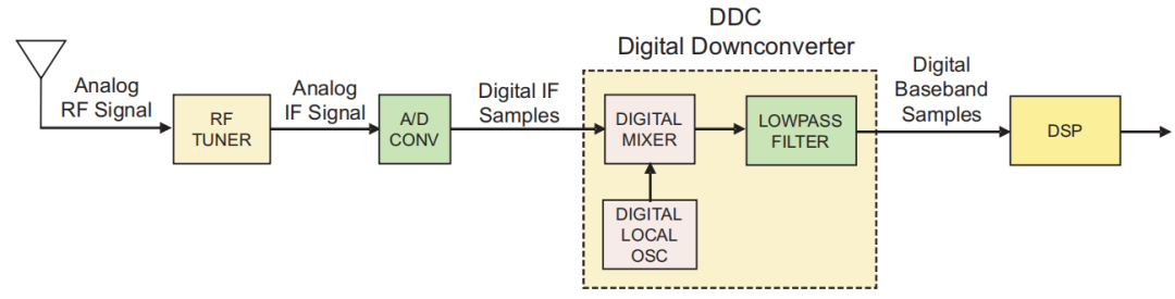
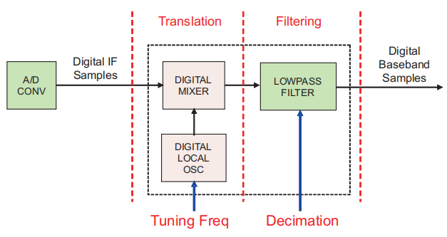
An analog-to-digital converter (A/D) then digitizes the IF, producing digital samples. Those samples are passed to the digital downconverter (DDC) shown inside the dashed box. The DDC is often implemented as a discrete chip or an FPGA IP core and is a key component of an SDR system.
Digital Downconversion (DDC)
A typical DDC contains three main elements:
- Digital mixer
- Digital local oscillator
- FIR low-pass filter
The digital mixer and LO translate the digital IF samples down to baseband. The FIR low-pass filter limits the signal bandwidth and functions as a decimating low-pass filter. The DDC uses many hardware multipliers, adders, and registers to perform these operations. The resulting digital baseband samples are then sent to digital signal processing modules for demodulation, decoding, and other tasks. These functions are typically implemented using dedicated ASICs and programmable DSPs. At the mixer output, the wideband samples from the A/D have been downconverted to complex I and Q baseband, with the frequency shift determined by the LO.
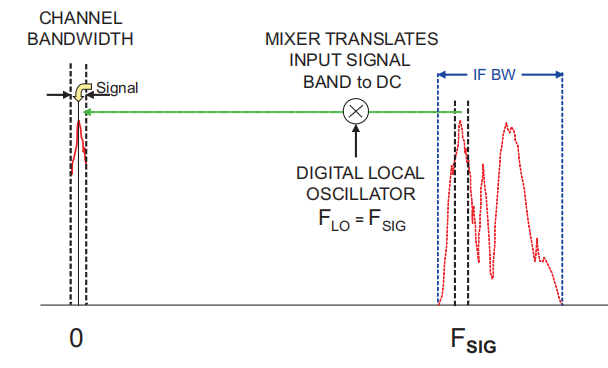
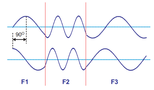
This is similar to the analog mixer, but here the mixing is performed digitally at IF. By tuning the LO within its operating range, any portion of the RF input can be mixed to baseband. In effect, the wideband RF spectrum can be shifted around 0 Hz by changing the LO. Note that upper and lower sidebands are preserved. Because the LO is implemented with a digital phase accumulator, it has useful properties: frequency switching is phase-continuous, enabling accurate generation of FSK or sweeps as shown.
Frequency accuracy and stability are determined entirely by the A/D clock, so the LO is inherently synchronized to the sampling frequency. Being purely digital, the LO does not suffer aging, drift, or calibration issues.
Decimation Filtering
Because the FIR filter output is bandlimited, the Nyquist theorem allows us to reduce the sampling rate. If we keep one sample out of every N input samples, we reduce the sample rate by a factor of N.
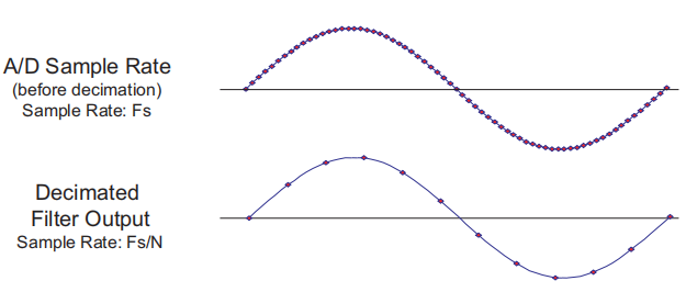
This process, called decimation, means retaining only one of every N samples. If the decimated output sample rate is at least twice the output bandwidth, no information is lost. The advantages are lower processing bandwidth, lower transmission rates, and reduced memory usage, which reduce system cost. The DDC performs two signal-processing operations: 1) frequency translation controlled by the LO, and 2) low-pass filtering with bandwidth controlled by the decimation setting.
Software-Defined Radio Transmitter
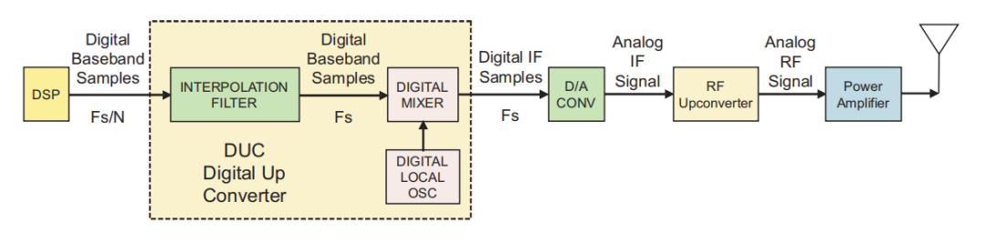
Now consider the SDR transmitter. The input to the SDR transmitter is a digital baseband signal, typically produced by the DSP stage, as shown below.
Digital Upconversion (DUC)
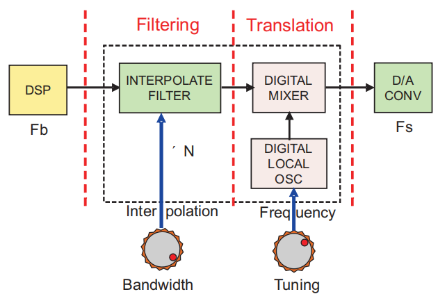
The digital hardware block in the dashed box is the digital upconverter (DUC), which translates the baseband signal to an IF. A digital-to-analog converter (D/A) then converts the digital IF samples to an analog IF. An RF upconverter translates the analog IF to RF. Finally, a power amplifier increases the signal energy and sends it to the antenna. The DUC internals are shown below: the mixer and LO on the right translate baseband samples to the IF. The IF translation frequency is set by the LO.
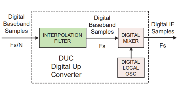
The mixer produces one output sample for each of its two input samples. The mixer output sampling rate must equal the D/A sampling rate fs. Therefore, the LO sampling rate and the baseband sampling rate must be compatible with fs. The LO already operates at fs, but the baseband input rate is typically much lower. This mismatch is solved with an interpolation filter.
Interpolation Filtering
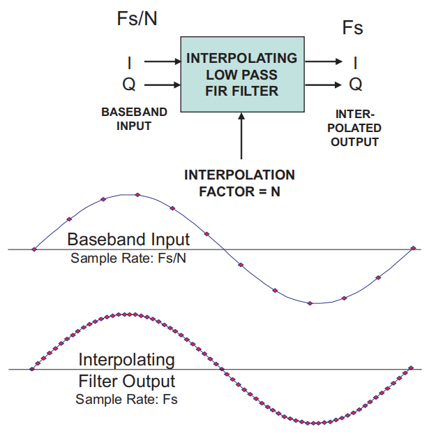
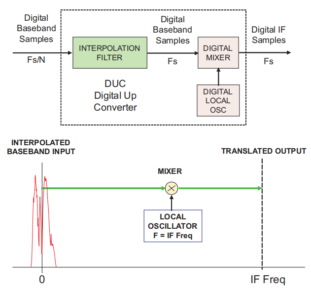
An interpolation filter increases the baseband input sample rate fs/N up to the sampling rate fs required by the mixer inputs and the D/A output. The interpolation factor N raises the sample rate by inserting additional samples between original input samples while preserving the baseband spectral information. The interpolation operation is the inverse of the decimation filter discussed earlier. The digital upconversion frequency-domain behavior is shown below.
The LO is set to the required IF frequency, as with the DDC. The DUC performs two processing steps: interpolation to increase the sample rate, and frequency translation to shift the baseband to IF.
The ratio of the required output sampling rate to the input baseband sampling rate determines the interpolation factor N.
The baseband bandwidth equations assume a complex I+Q baseband and typical 80% passband filter characteristics. The "bandwidth control" corresponds to the programmable interpolation or decimation setting that selects the desired baseband bandwidth. Using the LO and mixer, the baseband is translated up to the IF. The LO frequency is programmable to select the desired IF translation.