Iridium inter-satellite links
Iridium system
The Iridium space segment consists of 72 satellites (including 6 spares) distributed in six polar circular orbital planes. The constellation design ensures that at least one satellite is visible from any point on Earth at any time. Each satellite antenna provides 960 voice channels; up to two antennas per satellite can point to a single gateway, so a satellite can support up to 1,920 voice channels. Iridium satellites project 48 spot beams toward Earth to form 48 identical cells, each cell having a diameter of 689 km. The 48 spot beams together form a coverage area with an approximate diameter of 4,700 km. A user typically sees a given satellite for about 10 min. Each satellite has four inter-satellite links: one forward, one return, and two crosslinks. Inter-satellite link rates can reach up to 25 Mbps. In the L-band 10.5 MHz allocation the spectrum is divided into 12 FDMA bands and uses a TDMA structure with a 90 ms frame; each frame supports four 50 kbps user connections.
Iridium uses an MF-TDMA (multi-frequency time division multiple access) scheme for voice, which generally yields lower voice quality than CDMA. In addition, earlier Iridium data services were limited to about 2.4 kbps, allowing only short email or slow fax transmission, not suitable for general Internet access.
Constellation design
The Iridium constellation comprises six circular orbits with an inclination of 86.4°. This inclination misses passing directly over the geographic poles by 4.6°. The orbital planes are separated by 27°. There are 66 operational satellites evenly distributed across the six planes, with one spare per plane for a total of 72 in orbit. Each satellite is connected to its four adjacent satellites via inter-satellite links, creating a contiguous global network of orbital "base stations."
The orbital altitude is 780 km above the surface.
Phased array footprint and spot beams
The Iridium L-band phased-array antennas form the ground footprint, composed of 48 spot beams. Each spot beam covers roughly 600 km on average and provides 80 channels. With 48 beams covering about 4,700 km, the system offers a total of 3,840 channels, enough to support tens of thousands of users.
Right ascension of ascending node (RAAN)
RAAN is the angle from the vernal equinox to the orbit's ascending node, measured about the center of the Earth. The ascending node is the point where the satellite crosses the equatorial plane going from south to north. The opposite intersection is the descending node. The vernal equinox is the intersection of the ecliptic and the celestial equator. The RAAN and orbital inclination together uniquely determine the orientation of the orbital plane in space.
| Orbital Plane | RAAN (0–360°) |
|---|---|
| 1 | 31.6° |
| 2 | 63.2° |
| 3 | 94.8° |
| 4 | 126.4° |
| 5 | 158.3° |
| 6 | 189.6° |
RAAN and inclination
The RAAN Ω and the orbital inclination i define the relative orientation between the satellite orbital plane and the Earth. The orbit plane intersects the equatorial plane at two nodes. When the satellite moves from the southern hemisphere across the equator into the northern hemisphere, the intersection point is the ascending node; the opposite intersection is the descending node. The RAAN is measured from the vernal equinox to the ascending node in the direction of increasing right ascension. Together, inclination and RAAN determine the orbit plane's orientation in space.
Initial argument of latitude
The initial argument of latitude is the angle of the satellite on the auxiliary circle relative to the center. It differs in measurement from other perigee-related angles. The argument of latitude varies linearly with time, which simplifies the computation of travel time between two points on the orbit.
| Satellite | Initial argument of latitude (degrees) | |
|---|---|---|
| Odd-numbered plane | Even-numbered plane | |
| 1 | 0 | 0.5 × 360/11 |
| 2 | 360/11 | 1.5 × 360/11 |
| 3 | 2 × 360/11 | 2.5 × 360/11 |
| 4 | 3 × 360/11 | 3.5 × 360/11 |
| 5 | 4 × 360/11 | 4.5 × 360/11 |
| 6 | 5 × 360/11 | 5.5 × 360/11 |
| 7 | 6 × 360/11 | 6.5 × 360/11 |
| 8 | 7 × 360/11 | 7.5 × 360/11 |
| 9 | 8 × 360/11 | 8.5 × 360/11 |
| 10 | 9 × 360/11 | 9.5 × 360/11 |
| 11 | 10 × 360/11 | 10.5 × 360/11 |
Signal architecture
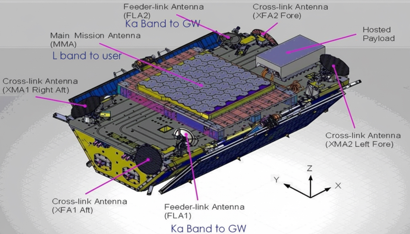
The Iridium signal architecture uses regenerative on-board processing with an on-board processor. Key RF payload features include a single 48-beam transmit/receive phased-array antenna, a TDD architecture, two steerable 20/30 GHz feeder links to terrestrial gateways, four 23 GHz crosslinks to adjacent Iridium NEXT satellites for relay communications (two steerable and two fixed antennas with TDD), and 20/30 GHz links via omni antennas.
Iridium NEXT parameters
| Iridium NEXT constellation | 66 operational satellites in 6 planes of 11 spacecraft each |
| Orbit | Polar LEO at an altitude of 780 km |
| Inclination | 86.4° |
| Period | 101 minutes per orbit |
| Launch period | 2015–2017 |
| Mission life | 15 years to beyond 2030 |
| Risk mitigation | 6 in-orbit spares + 6 ground spares |
| Spacecraft launch mass, power | ~860 kg, 2 kW |
| Spacecraft dimensions (stowed) | 3.1 m × 2.4 m × 1.5 m |
| Deployed wingspan | 9.4 m |
| Spacecraft stabilization | 2-axis attitude control. A total of 248 AA-STR star trackers supplied for the Iridium NEXT constellation. |
| RF communications | Regenerative processing payload with OBP (On-Board Processor). Key features:
|
Link parameters (user, gateway, and satellite links)
| Satellite–User (ISU) | Satellite–Gateway | Satellite–Satellite | |||
|---|---|---|---|---|---|
| Downlink | Uplink | Downlink | Uplink | ||
| Multiple access | TDMA/FDMA | TDM/FDMA | TDM/FDMA | ||
| Modulation | QPSK | QPSK | QPSK | ||
| Baseband filtering | 40% raised cosine | Filtered | Filtered | ||
| FEC rate | 3/4 | 1/2 | 1/2 | 1/2 | |
| Encoded data rate (Mbps) | 0.05 | 0.05 | 6.25 | 6.25 | 25 |
| Channel bandwidth (kHz) | 31.5 | 31.5 | 4,375 | 4,375 | 17,500 |
| Center frequency (GHz) | 1.62125 | 1.62125 | 20 | 29.40 | 23.28 |
| Total bandwidth (MHz) | 10.5 | 10.5 | 100 | 100 | 200 |
| Carrier spacing (MHz) | 0.04167 | 0.04167 | 7.5 | 7.5 | 25 |
| Polarization | Right-hand circular | Right-hand circular | Vertical | ||
| Satellite EIRP (dBW) | 7.5–27.5 | 13.3–23.2 | 38.4 | ||
| Satellite G/T (dBi/K) | -10.6 to -3 | -1.0 | 8.1 | ||
| Satellite amplifier output power (W) | 0.1–3.5 per carrier | 0.1–1.0 per carrier | 3.4 per carrier | ||
| Satellite receive system noise temperature (K) | 500 | 1,295 | 720 | ||
| Capacity per satellite | 3,840 | 3,840 | 3,000 | 3,000 | 6,000 |
Inter-satellite links (ISL)
Ka-band ISL
Inter-satellite links can use RF or optical carriers depending on capacity and power considerations. Lower-rate links often use RF, while higher-rate links use optical communications. Ka and EHF bands provide abundant spectrum with available bandwidths of several GHz, making them attractive for wideband satellite communications. Using Ka-band enables narrower beams, higher EIRP, and reduced transmit antenna size. For ISLs, the advantages are greater: favorable free-space propagation, narrow beams, concentrated energy, smaller and lighter equipment, and improved security and resistance to interference.
Iridium uses a 23 GHz ISL, while some systems use 60 GHz. Atmospheric absorption affects these bands: water vapor produces an absorption peak near 23.5 GHz, and oxygen produces a peak near 60 GHz. Because of atmospheric absorption, these bands are typically not used for terrestrial uplinks and downlinks; however, inter-satellite links operate in free space and are not affected by atmospheric absorption.
Iridium inter-satellite link design choices reflect trade-offs among capacity, power, and equipment complexity. Typical Iridium ISL characteristics:
- Four ISL antennas per satellite, with aperture diameters of roughly 60 cm.
- Antenna gain around 36 dBi with a steerable radiation pattern.
- Reported EIRP about 38.4 dBW.
- Transmit amplifier power on the order of 2 dBW (about 1.6 W).
The four ISL antennas are angled to connect the Iridium network both upward and downward rather than being coplanar; two antennas look upward and two look downward.
Ka-band ISL operational considerations
Variation in inter-satellite distance requires link control such as automatic gain control at the receiver and power control at the transmitter. Iridium inter-satellite distances vary between about 4,500 km and 9,200 km.
In practice, antenna pointing error can be about 1/10 of the beamwidth, causing pointing loss on the order of 0.5 dB. Antenna noise temperature for ISL antennas, excluding solar contributions, can be around 10 K. Antenna sizes in practice range from about 1 m to 2 m. For a 60 GHz link with 1 dB receive loss, typical G/T values are on the order of 25–29 dB/K and required EIRP can be in the range of 72–78 dBW for certain scenarios. For a beamwidth of 0.2° (typical for a 2 m antenna at 60 GHz), a pointing accuracy of 0.1° toward the transmitting satellite is sufficient to acquire a beacon for tracking. For links between satellites with small angular separation, using narrow-beam antennas with reduced sidelobes helps avoid interference and supports frequency reuse. Constraints such as launcher volume and technology compatibility limit antenna size on satellites, which makes higher-frequency ISLs a practical choice for minimizing aperture while achieving necessary link performance.