Overview
This article briefly describes the main methods used to implement modulation and demodulation in radio systems, a topic that is important in the context of software-defined radio (SDR).
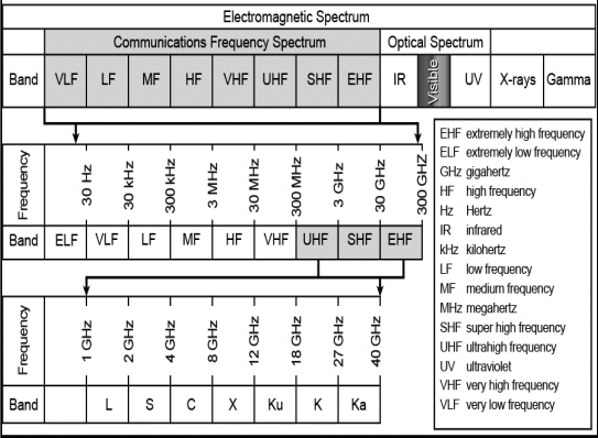
Heterodyne and Superheterodyne
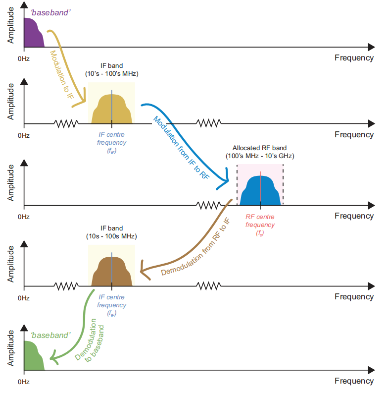
Transmitters typically use one of two architectures. The first performs a single-stage conversion from baseband directly to radio frequency (RF), commonly referred to as heterodyne. The second, the superheterodyne architecture, uses two conversion stages: baseband to intermediate frequency (IF), then IF to RF.
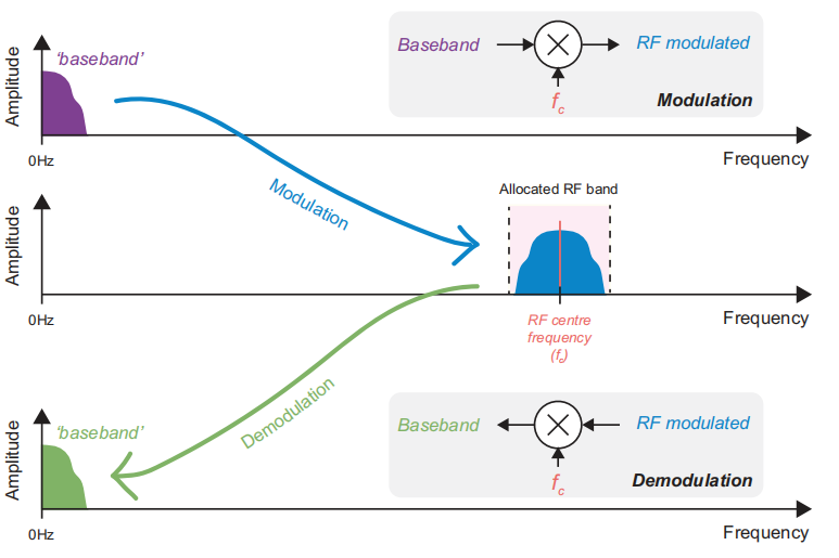
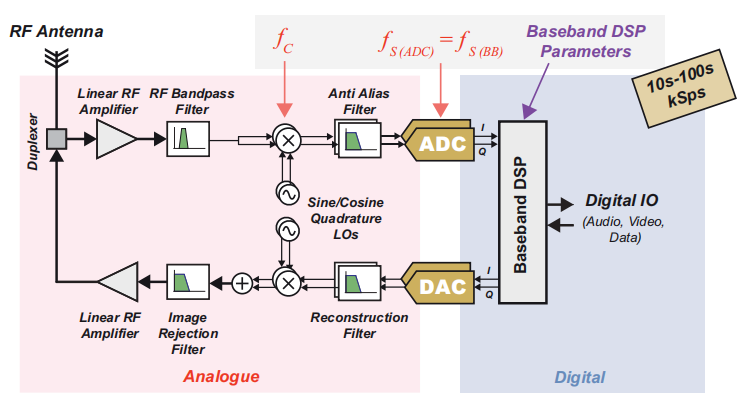
Figure 1 shows modulation and demodulation in the heterodyne case. A single-stage modulator converts the signal from baseband to RF, and a single-stage demodulator converts RF back to baseband.
Figure 2 illustrates a superheterodyne scheme and the frequency translations that occur. Note that IF signals are often in the tens to hundreds of MHz range, while the final RF band can be much higher, potentially up to tens of GHz.
Effect of Sampling Rate
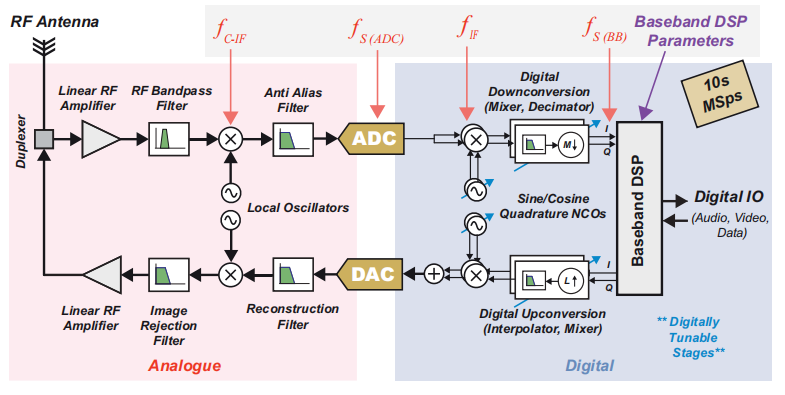
The sampling rates achievable by the digital components in an SDR, particularly the ADCs and DACs, determine which parts of the radio can be implemented digitally and which parts must remain analog. Digital processing is possible only when the Nyquist criterion is met. In other words, if the sampling rate is greater than twice the highest frequency component present in the signal, then, depending on the RF band used to carry the signal, it is possible to perform all modulation and demodulation in the digital domain. The Nyquist condition is illustrated below.
Here, fs is the ADC and DAC sampling rate and frf_max is the maximum frequency component present in the RF-modulated signal. If fs > 2 * frf_max, then all analog signal processing can be done digitally, enabling so-called direct-RF or almost-all-digital radio architectures.
If that condition cannot be met, another option is to perform modulation and demodulation between baseband and IF in the digital domain, while the IF-to-RF conversion is handled by analog circuitry. In that case the ADC is located in the IF band and sampling rates typically range from tens to hundreds of MHz.
Three simplified radio architectures arise based on the locations of the DAC and ADC. These simplified diagrams omit some required filtering stages for clarity.
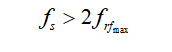
Direct-RF (Almost All-Digital) SDR
As ADC and DAC technology has improved, particularly in sampling rate, more bands can be implemented in an almost-all-digital manner. This architecture requires minimal analog processing, mainly the antenna, front-end filtering, and amplifiers. From an SDR perspective, implementing almost all functions digitally is important because it allows radio operation to be controlled in software, as shown in Figure 3.
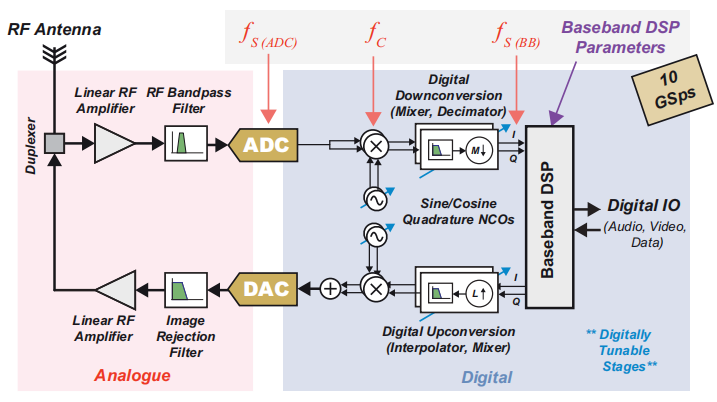
IF-Sampled SDR
When RF frequencies exceed the available ADC and DAC sampling rates, a superheterodyne conversion architecture can be used. Modulation and demodulation between baseband and IF are implemented in the digital portion of the radio, while IF-to-RF conversion uses analog circuitry. Even so, it is often possible to exert software control over analog mixing stages. When the ADC is placed at the IF frequency, the required sampling rate may range from tens to hundreds of MHz. An IF-sampled SDR architecture is illustrated in Figure 4.
Baseband-Sampled SDR
Another SDR class has the ADC operating at baseband rates, with all modulation and demodulation performed in the analog domain using either single-stage or two-stage conversion. Historically, this approach was used because of limits on ADC and DAC sampling rates; placing the A/D interface at baseband was the only feasible option. The baseband-sampled architecture may still be used in low-cost, low-data-rate devices to minimize digital processing requirements, or it can be combined with advanced multi-GSPS data converters for extremely wideband transmit and receive applications. See Figure 5.
Advantages of Digital Implementation
Comparing Figures 3 through 5 makes it clear that the higher the sampling rate of the ADC and DAC, the greater the amount of processing that can be done digitally.
Implementing modulation and demodulation digitally offers several advantages, including higher operational precision, reduced sensitivity to component tolerances and aging, smaller physical size, simplified bill of materials, and potentially lower power consumption.
Within the SDR context there are additional benefits from increased software control over radio operation and the resulting flexibility. When using FPGAs or SoCs, hardware reprogrammability enables more fundamental upgrades and functional changes.
Key Radio Terms and Parameters
Before continuing, it is useful to define key terms and concepts that will appear frequently when discussing SDR and radio systems in general. These are illustrated in Figure 6 and described below.
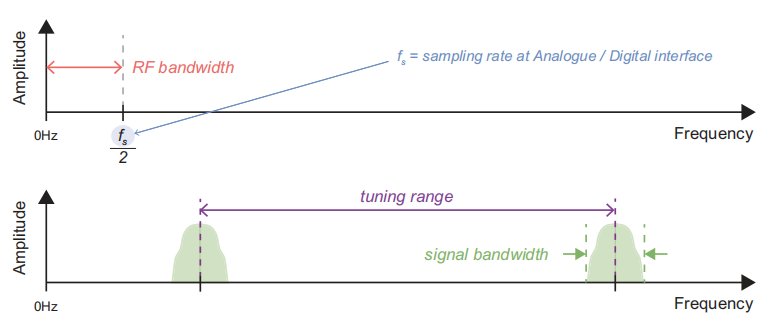
RF Bandwidth
RF bandwidth describes the frequency range that a radio transceiver can generate or capture. In the SDR context this relates to the ADC and DAC sampling rates. For a single real ADC and DAC, RF bandwidth is half the sampling frequency. If complex I/Q input and output are used, RF bandwidth can double to the full sampling frequency, but this requires a pair of ADCs and DACs. Complex signaling is discussed separately in later material.
Signal Bandwidth
Signal bandwidth refers to the frequency span occupied by the transmitted signal. Using SDR, the signal bandwidth is a design parameter that can be defined in software. For example, a transmitter may generate a 10 kHz or a 100 MHz bandwidth signal depending on configuration. Generally, larger bandwidths enable higher data rates. The maximum signal bandwidth is limited by the SDR hardware RF bandwidth.
Tuning Range
Tuning range denotes how far the RF bandwidth can be moved when using IF-sampled or baseband-sampled architectures, where part or all of modulation and demodulation occurs in the analog domain. The available tuning range depends on the analog circuitry, so SDRs with tuning stages typically specify lower and upper tuning frequencies in their documentation. For direct-RF architectures, modulation and demodulation occur entirely in the digital domain, so there is no analog tuning stage.