Introduction
Electronic tags, as core components of modern IoT systems, rely on the internal chip's structure and functional modules to achieve efficient and accurate identification and tracking. Many readers are not familiar with the characteristics and architecture of these chips, so this article provides a detailed explanation of electronic tag chips.
1. Structure of Electronic Tag Chips
The circuitry of electronic tag chips is complex and refined. The main components include the power circuit, clock circuit, demodulator, codec, controller, memory, and load modulation circuit, as shown below.
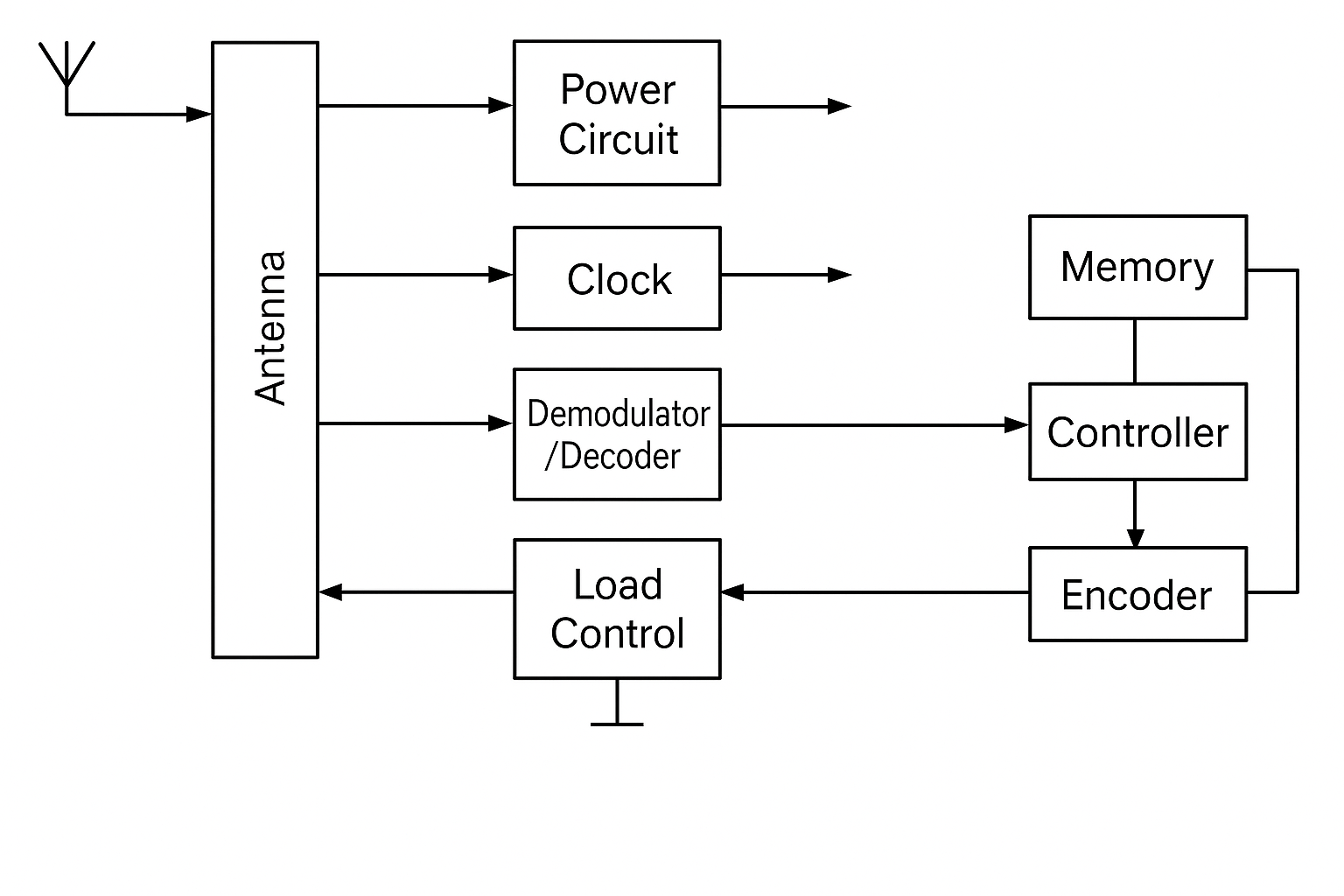
1. Power circuit
Responsible for rectifying the radio frequency signal received by the antenna into DC energy to provide a stable operating voltage for the chip. Design considerations include antenna matching, power and voltage efficiency, data modulation compatibility, and circuit complexity.
2. Clock circuit
Provides accurate clock signals to internal modules to ensure data synchronization and processing speed. The clock source typically derives from the carrier signal received by the tag antenna and is divided down for the codec, memory, and controller.
3. Data input/output module
Handles reception of commands and data from the reader, demodulating and decoding them before forwarding to the controller. It also encodes and modulates internal data for transmission through the antenna to the reader.
2. Functions of the Different Modules
1. Demodulator and codec
The demodulator converts received RF signals into baseband signals. The codec converts baseband signals into digital data and encodes digital data into baseband signals suitable for transmission.
2. Controller
The controller is the chip's core. It executes commands from the reader, manages read and write operations, and coordinates the operation of the various modules.
3. Memory
Stores the tag's identifier, configuration data, and other key information. Its capacity and read/write speed directly affect tag performance and application scope.
4. Load modulation circuit
During transmission, this circuit modulates the encoded digital signal onto the RF carrier and transmits it via the antenna.