A key difference between ordinary circuits that operate at low frequencies and circuits designed for RF frequencies is their electrical size. RF designs can involve dimensions that are a significant fraction of the wavelength, causing the magnitude and phase of voltage and current to vary with the physical size of components. These effects establish fundamental principles for RF circuit design and analysis.
Basic concepts and terminology
Consider a transmission line terminated in an arbitrary load (for example, a coaxial cable or microstrip), and define wave quantities a and b as shown in Figure 1.
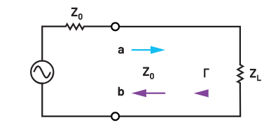
Figure 1. A transmission line terminated in a single-ended load matched to a signal source.
These wave quantities are the complex amplitudes of the voltage waves incident on and reflected from the load. We can use them to define the voltage reflection coefficient Γ, which describes the ratio of the complex amplitude of the reflected wave to that of the incident wave:
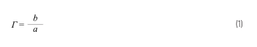
The reflection coefficient can also be expressed in terms of the characteristic impedance Z0 of the transmission line and the complex input impedance of the load ZL:
In RF engineering, Z0 = 50 Ω is commonly used; this is a compromise between signal attenuation and power handling capability and can be implemented with coaxial cable. In some applications, for example broadcast systems that require long-distance RF transmission, Z0 = 75 Ω is more common to reduce cable loss.
Regardless of the value of the characteristic impedance, the load is matched to the transmission line when the load impedance equals Z0. Note that this condition is only meaningful when the signal source is matched to the transmission line, as shown in Figure 1; this article makes that assumption. In that case, no reflected wave is produced (Γ = 0), and the power delivered to the load from the source is maximized, while under full reflection (|Γ| = 1) no power is delivered to the load.
If the load is mismatched (ZL ≠ Z0), not all incident power is absorbed. The corresponding power "loss" is described by the return loss (RL), which is related to the magnitude of the reflection coefficient and can be expressed as:
Return loss is the ratio of the incident power on the load to the power reflected back. Return loss is always non-negative and indicates the degree of matching between the load and the impedance that the network "presents" toward the source.
If the load is mismatched, the presence of reflected waves produces standing waves, causing the voltage amplitude to vary with position along the line. The parameter used to quantify line impedance mismatch is the standing wave ratio (SWR), defined as:
Because SWR is usually expressed using maximum and minimum voltages, it is also called the voltage standing wave ratio (VSWR). SWR is a real number ranging from 1 to infinity, with SWR = 1 indicating a matched load.
Conclusion
RF circuits have several fundamental characteristics that differ from ordinary circuits. Designing and analyzing microwave circuits requires extended concepts to address practical issues. This article presented and discussed several important concepts and terms related to wave reflection, a primary characteristic of RF systems.