Overview
The wireless receiver is a core element of a wireless communication system, and its performance directly affects overall communication quality. Key receiver performance metrics include sensitivity, adjacent/inter-channel selectivity, single-frequency desensitization, blocking from interferers, and dynamic range. Sensitivity is one of the most important of these metrics.
This article explains the receiver sensitivity metric.
Definition
Receiver sensitivity is the minimum RF input power required to achieve the system's specified error rate, expressed as the minimum signal-to-noise ratio needed to meet that error rate. The error rate may be bit error rate or frame error rate. Sensitivity depends on modulation and signal characteristics, the signal propagation channel, and other noise levels. Different communication systems have different sensitivity requirements.
Typical Sensitivity Ranges
- Bluetooth: -70 dBm to -100 dBm
- Wi-Fi: -40 dBm to -80 dBm
- Cellular: up to -120 dBm
- LoRa: up to -130 dBm
- GNSS: -140 dBm to -165 dBm
- ZigBee: -85 dBm to -92 dBm
Converted to milliwatts, these values are extremely small, illustrating the sensitivity of modern receivers:
- Bluetooth: 1e-7 mW to 1e-10 mW
- Wi-Fi: 1e-4 mW to 1e-8 mW
- Cellular: up to 1e-12 mW
- LoRa: up to 1e-13 mW
- GNSS: 1e-14 mW to 3.1623e-17 mW
- ZigBee: 3.1623e-9 mW to 6.3096e-10 mW
Satellite navigation systems achieve the lowest levels, down to about -165 dBm, which approaches the thermal noise floor.
Sensitivity Calculation
The sensitivity of a receiver can be derived from its noise figure. Before defining noise figure, it is useful to distinguish carrier-to-noise ratio (CNR) from signal-to-noise ratio (SNR). CNR refers to the ratio of RF or analog baseband carrier power to noise power within the signal bandwidth. Noise figure (NF) is defined as the ratio of input CNR to output CNR.
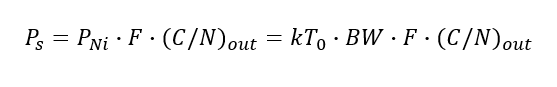
In the formula above, Ps is the desired signal power at the receiver input. PNi is the integrated thermal noise power within the receiver bandwidth BW. Under conjugate matching, the integrated thermal noise power PNi can be expressed as:
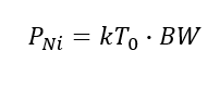
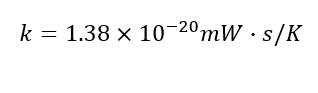
In the equation, k is Boltzmann's constant:
T0 is the reference temperature, typically T0 = 290 K. Rearranging yields the required signal power Ps at the receiver input:
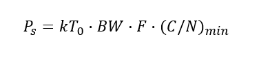
If the minimum required output CNR to meet the specified error rate is (C/N)min, then:
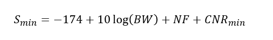
Expressed in the RF convention of dBm, Smin(dBm) becomes:

Which simplifies to the familiar sensitivity formula:
In this formula, ...
Thermal Noise by Bandwidth
For a given communication system, carrier bandwidth BW is known. The corresponding thermal noise power for different bandwidths is:
| Carrier bandwidth BW | Thermal noise power | Notes |
|---|---|---|
| 1 Hz | -174 dBm | |
| 10 Hz | -164 dBm | |
| 100 Hz | -154 dBm | |
| 1 kHz | -144 dBm | |
| 10 kHz | -134 dBm | FM radio channel for hand-held radios |
| 100 kHz | -124 dBm | |
| 180 kHz | -121.45 dBm | One LTE resource block |
| 200 kHz | -121 dBm | GSM channel |
| 1 MHz | -114 dBm | Bluetooth channel |
| 2 MHz | -111 dBm | Commercial GPS channel |
| 3.84 MHz | -108 dBm | UMTS channel |
| 6 MHz | -106 dBm | Analog TV channel |
| 20 MHz | -101 dBm | WLAN 802.11 channel |
| 40 MHz | -98 dBm | WLAN 802.11n 40 MHz channel |
| 80 MHz | -95 dBm | WLAN 802.11ac 80 MHz channel |
| 160 MHz | -92 dBm | WLAN 802.11ac 160 MHz channel |
| 1 GHz | -84 dBm | Ultra-wide channel |
Relation to Noise Figure and a Worked Example
Besides bandwidth, the minimum required CNR is defined by the wireless communication standard for a given error rate. Thus sensitivity is directly related to the receiver noise figure (NF). For example, consider a CDMA mobile receiver where the minimum CNR to achieve a frame error rate of 0.5% is 1 dB, and the receiver bandwidth is 1.25 MHz. The sensitivity is then:
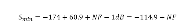
If the receiver noise figure NF = 6 dB, the sensitivity for this mobile receiver is -108.9 dBm. In other words, achieving the target sensitivity relies on designing for a low noise figure, which in turn depends on the components in the receive chain, such as antenna loss, filter insertion loss (IL), and the gain of the low-noise amplifier (LNA).
Improving Receiver Sensitivity
To improve sensitivity, the design goal is to reduce the overall noise figure of the receive chain. Key factors include minimizing antenna and front-end losses, selecting low-insertion-loss filters, and using a high-performance LNA with sufficient gain and low noise figure.