Introduction
In recent years, rapid advances in computer technology and artificial intelligence have driven robotic technology into a key area of research. Service robots have opened new application domains for robotics. As living standards improve, people place higher value on healthier, more comfortable homes. Routine cleaning after renovation can be time consuming and exhausting, and robot vacuums have become a common household appliance for many families.
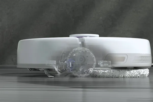
A robotic vacuum integrates mechanics, electronics, sensor technology, computing, control, robotics, and artificial intelligence. As one of the earliest practical mobile robots, robotic vacuums typically use brushes and suction to collect floor debris into an internal dustbin. Typical models are battery powered, disc-shaped, and operate via remote control or onboard buttons. Common features include scheduling, automatic return to charge, ultrasonic distance sensing for obstacle detection, and basic path planning to cover rooms systematically.
Working Principle and Features
Robotic vacuums are microcomputer-controlled and can perform automatic navigation for sweeping and vacuuming. Collision bumpers help avoid or circumvent obstacles and reach corners. Large side brushes improve corner cleaning, and rotating brushes help direct debris toward the suction inlet. Integrated sensors such as optical sensors on the powertrain help detect brush or drive motor jams and trigger automatic reverse or shutdown. Infrared cliff sensors prevent falls by detecting drop-offs and prompting the robot to avoid them.
Key features:
- Time and labor savings: cleaning is automated, reducing manual effort and freeing time for other activities.
- Low noise: many models produce less than 50 dB during operation.
- Air improvement: some designs include activated carbon or filters to adsorb harmful substances.
- Compact form factor: small size enables cleaning in corners and under furniture where upright vacuums cannot reach.
System Overview and Key Technologies
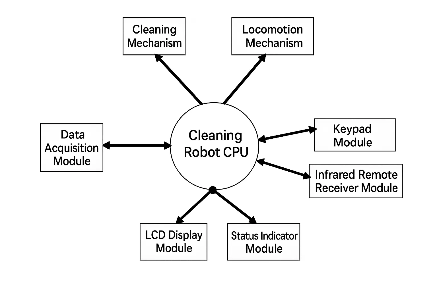
A robotic vacuum system typically consists of four parts: locomotion, perception (sensing), control, and the suction/cleaning subsystem. The locomotion mechanism forms the robot body and usually uses a wheeled drive to determine motion range. The perception system commonly uses ultrasonic rangefinders, contact and proximity sensors, infrared sensors, and CCD cameras.
Recent progress in computing, artificial intelligence, sensing, and mobile robotics provides a solid foundation for robotic vacuum control systems. Because the operating environment is often uncertain or dynamic, control solutions must balance safety, reliability, robustness to interference, and cleaning effectiveness. Sensor-based environment detection, signal analysis, and suitable modeling techniques are essential. For autonomous mobile robots in unstructured environments, improvements in automation rely on obstacle recognition, real-time data transmission, appropriate AI methods, and development of global models to provide global information to the robot.
Rapidly evolving technologies that strongly affect robotic vacuum development include sensing, intelligent control, path planning, cleaning mechanics, and power systems.
Mechanical Structure
Major mechanical components typically include:
- Drive wheels and drive motors. These enable planar movement. Infrared switches on the front and sides act as collision detectors, and three infrared switches on the underside detect steps to prevent falls. Drive wheels often include optical encoders for speed measurement and closed-loop control, enabling positioning and path planning. Ultrasonic sensors may be added for more precise localization.
- Brush assembly. Motors drive two sweeping brushes: the left brush rotates clockwise and the right brush rotates counterclockwise to funnel debris toward the suction inlet.
- Suction unit. Generates suction force to pull dust into the dust storage bin.
- Mopping/cloth wiping assembly. A cleaning cloth mounted under the chassis wipes residual fine dust after sweeping and vacuuming to improve final cleanliness.
Operational Workflow
Typical operating sequence:
- Start cleaning via onboard buttons or remote control.
- Once active, the robot runs the sweeping, vacuuming, and wiping modules.
- Sensors continuously collect external information and send it to the CPU for analysis and path decision making.
- When path planning requires turning, the CPU adjusts left and right wheel speeds and uses differential drive to steer.
- During operation, an LCD can display status information such as mode, runtime, or temperature.
- The remote can also schedule start/stop times or set timed operation.
The robot uses installed sensors to obtain indoor environment and self-state information such as obstacle locations and traveled distances. Based on that data, the control strategy is selected and implemented by a microcontroller to perform obstacle detection, avoidance, and motion control. The control panel provides start/stop buttons, and remote scheduling with LCD countdown and temperature display is common.
Sensor System
Sensors are fundamental for robotic intelligence. Continuous perception of the environment enables appropriate decision making and action selection.
Ultrasonic Sensors
Ultrasonic waves travel at a constant speed in a given medium and reflect at boundaries between different media. By measuring the time interval between emission and reception of a pulse, distance can be calculated:
s = v × t / 2
Where s is the distance to the obstacle, t is the round-trip time, and v is the speed of sound in air. Obstacle avoidance in many robots uses ultrasonic ranging. A typical sensor array may include three pairs (each pair with a transmitter and a receiver), for a total of six ultrasonic transducers. A 40 kHz oscillation signal of about 5 V is applied to the transmit transducer to produce ultrasonic pulses. Reflected echoes received by the receiver transducer are processed to determine obstacle distance and, by amplitude, an estimate of obstacle size.
Direct reflection detection is used: the transducer emits sound and detects partial reflections returned from objects. The microcontroller processes the signals to estimate object size and distance.
Infrared Range Sensors
Infrared range sensors detect obstacle distance by measuring variation in reflected infrared intensity. Each sensor typically contains an IR emitter diode and an IR receiver. When IR emitted toward an obstacle is reflected back, the receiver captures it, and processing of the returned signal allows environment change detection.
Contact Sensors
Contact thickness sensors measure via inductive displacement sensors, capacitive displacement sensors, potentiometric displacement sensors, Hall-effect displacement sensors, etc. For continuous measurement on moving objects, a rolling contact tip is often used to reduce wear. Contact sensors measure height and object size; a robot can use them to detect obstacle height and make corresponding decisions.
Infrared Photoelectric Sensors
For turbidity or optical detection, an infrared LED emits light that traverses the medium and is received by a phototransistor. Particle size and density change the received photocurrent approximately linearly. After filtering, the output signal correlates with turbidity or particulate concentration.
Collision Sensors
To detect collisions, optical switch sensors can sense impact and approximate contact location so the robot can respond. A front-mounted bumper with approximately 180° coverage typically houses optical switches on both sides. Each optical switch consists of an IR emitter and a photodiode; when a collision blocks the light path, the switch state changes and notifies the control system. This arrangement reduces blind zones and enables direction-based responses to collisions.
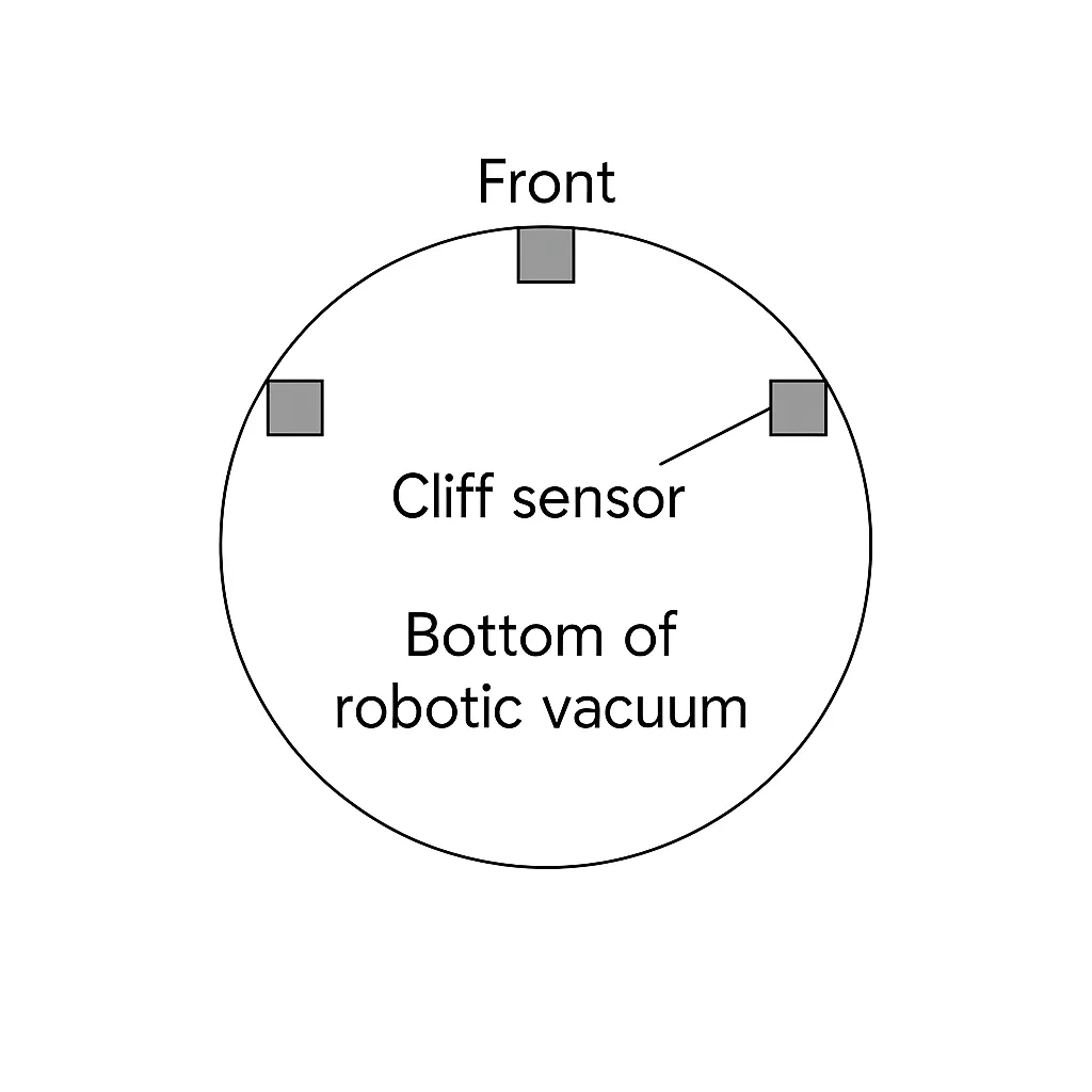
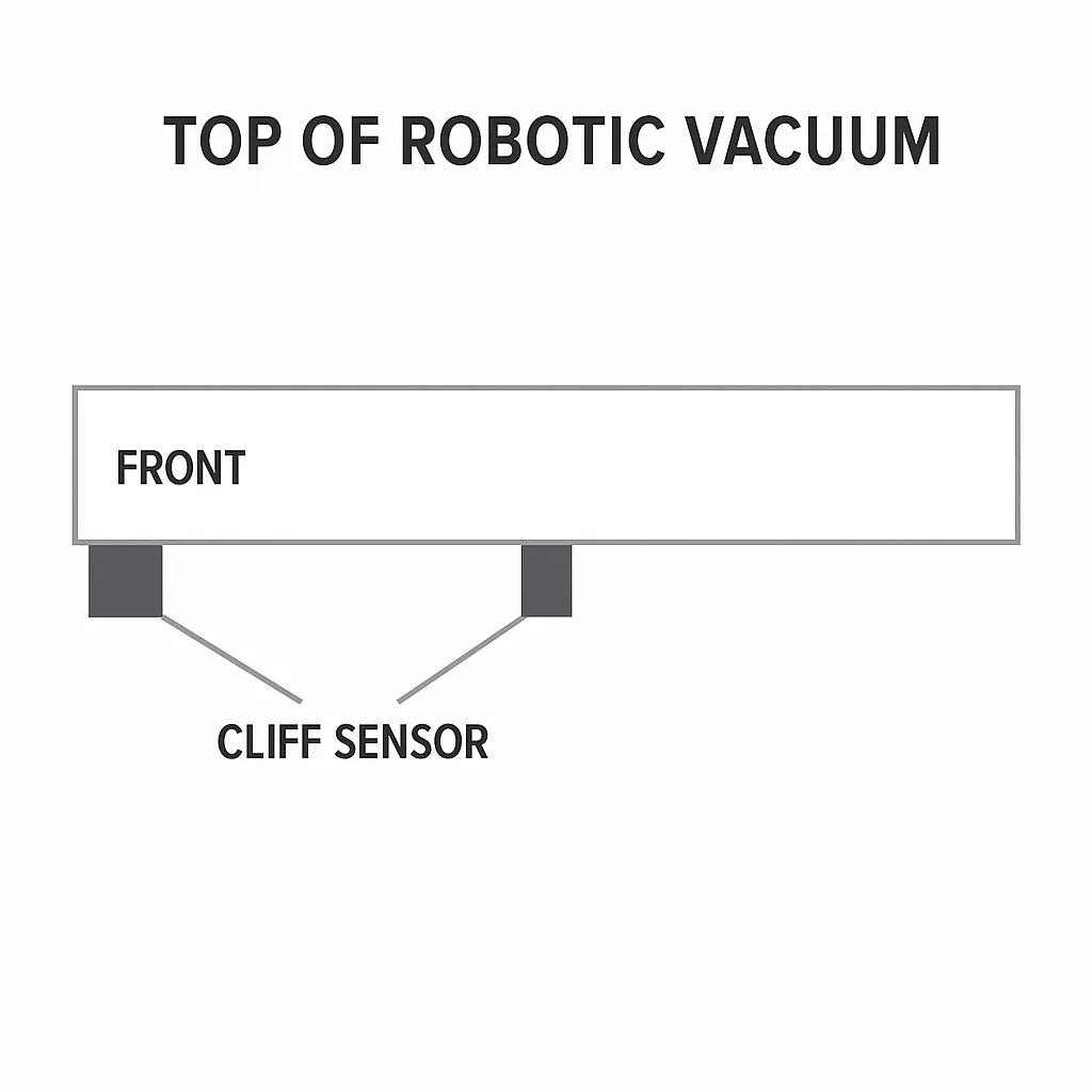
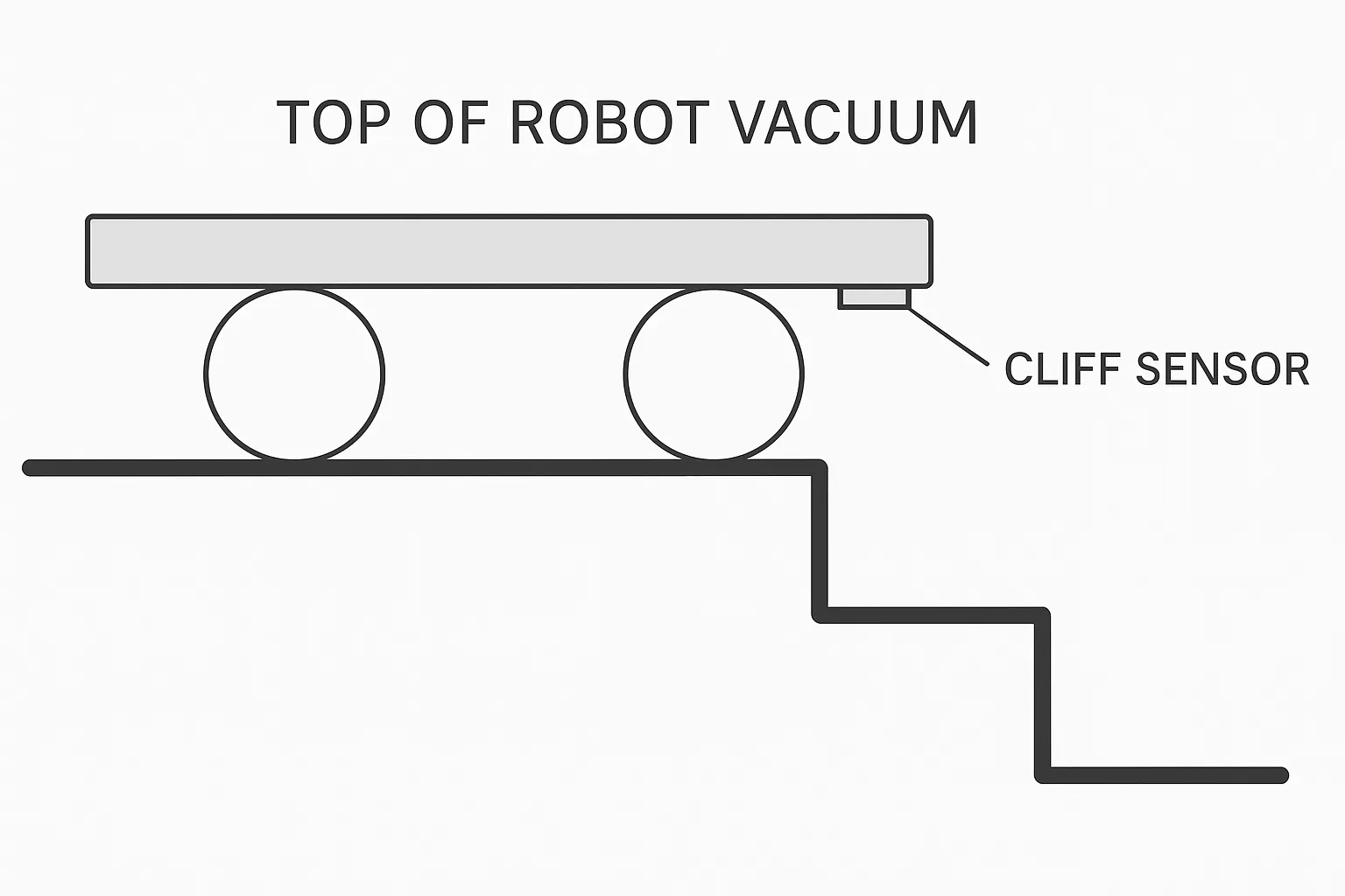
Cliff Detection (Anti-Fall) Sensors
Cliff sensors prevent falls at edges or stairs. Typically three cliff sensors are mounted at the rear. These sensors often use ultrasonic ranging: when the robot approaches a ledge, the sensor measures the distance to the ground. If the distance exceeds a threshold, the sensor signals the controller and the robot turns to avoid falling.
Overheat Protection Sensors
To prevent motor overheating and potential circuit damage, temperature sensors are mounted on the robot's circuit board. When motor temperature exceeds a limit, a sensor signals the controller, which stops operation and runs a cooling fan. When temperature drops to a safe level, another sensor signals the controller to resume operation.
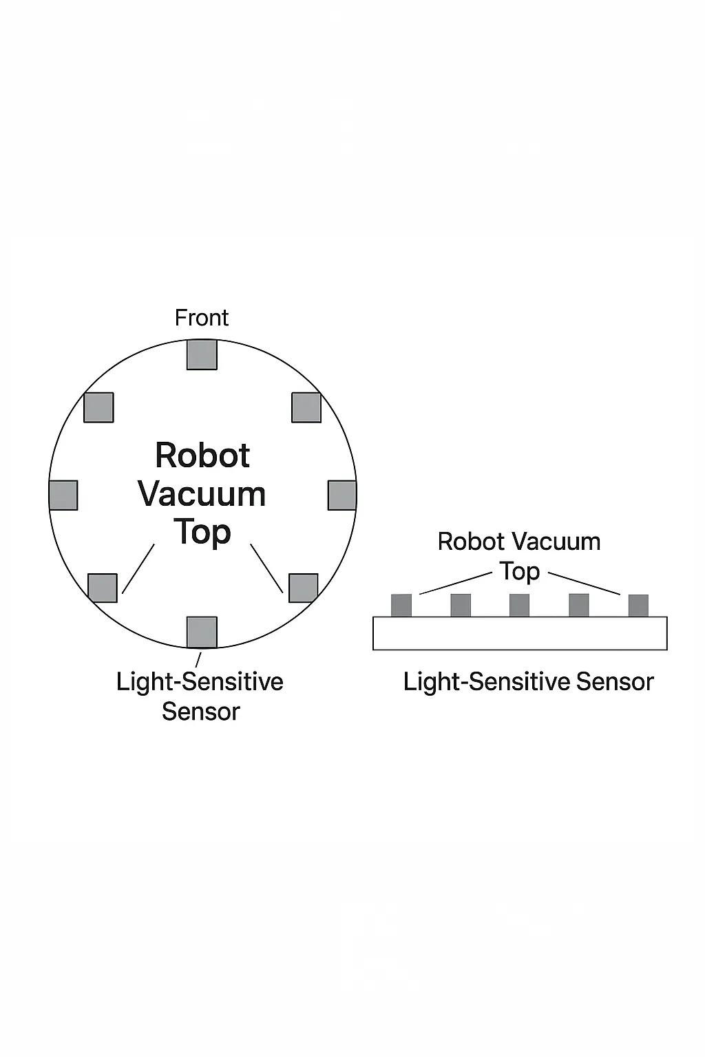
Under-Furniture Deep Cleaning
Areas under beds, sofas, and cabinets often accumulate more dirt. To prioritize these areas, light sensors are mounted at the front. When operating under low light, the sensors detect reduced light intensity and signal the controller to continue cleaning the dark area; when light increases (indicating exit from beneath furniture), the robot can reorient and return to the dark zone to continue cleaning.
Dust Bin Full Sensor
Capacitive sensors are mounted beside the dustbin to detect when the dust level reaches the sensor height. As dust accumulates, the effective dielectric constant changes, causing the sensor capacitance to change. The sensor notifies the controller, which can trigger an alert to indicate the dustbin needs emptying.
Low Battery Auto-Return
Because battery capacity is limited, robots typically return to their charging dock when battery level falls below a threshold. The controller activates an IR transmitter; the dock equipped with an IR sensor responds. The robot's IR receiver detects the dock's signal and the controller guides the robot toward the docking station for recharging.
Edge Detection Sensor
Edge detection often uses a mechanical switch with a roller-type trigger mounted on both sides of the robot, ensuring the robot can follow walls closely and better clean wall-adjacent corners.
Optical Encoder
Incremental optical encoders measure wheel rotation and speed. The encoder is coaxially connected to the drive motor through a gearbox and outputs pulses corresponding to motor shaft rotation. By converting pulse counts to wheel rotation angle using known gear ratios and dimensions, the system estimates the robot's odometry relative to a reference point. Optical encoders are widely used for measuring angular speed and position in motor drives and steering mechanisms and provide reliable body-frame position estimates.
Electronic Compass
An electronic compass measures orientation relative to the Earth's magnetic field. Modules integrate high-reliability magnetic sensors and driver chips to provide high precision and interference rejection. Multiple orthogonal magnetic sensors enable three-dimensional angle measurement to determine current heading. A horizontal-plane angle relative to the magnetic field is sufficient to get the robot's direction.
Gyroscope
Because electronic compasses can be affected by electromagnetic interference and encoders can be affected by wheel slip, gyroscopes provide accurate measurements of angle, angular velocity, and angular acceleration. They help maintain accurate orientation estimates under those disturbances.
Path Planning
Path planning finds a collision-free path from a start to a target that covers the desired cleaning area according to optimization criteria. Planning approaches vary depending on prior knowledge of the environment:
- Global path planning assumes a fully known environment.
- Local path planning assumes partial or unknown environment information and uses online sensor data to detect obstacles, shapes, and sizes.
Edge Learning for Unknown Areas
When the environment is unknown and infrared sensors are used, an edge-following strategy is effective. The robot can start from a specified position and circle the room along walls and near-wall obstacles in a clockwise or counterclockwise direction, recording center-point coordinates in real time. This produces a rough outline of the cleaning area and the distribution of wall-adjacent obstacles. The robot records maximum y (ymax) and corresponding maximum x (xmax) values to capture boundary extents, accounting for obstacles that may occupy corner regions.
During motion, the robot measures heading via angle sensors and displacement via optical encoders, integrates the trajectory to obtain current position in real time:
Full-Area Coverage Planning
To achieve systematic coverage, define movement rules to operate in straight, strip-like back-and-forth patterns when no obstacles are present. When an IR sensor detects the robot has reached the maximum x position, it performs a 180° turn about one drive wheel while the other wheel acts as a pivot, shifting laterally by one track width to avoid uncovered gaps.
If obstacles appear during motion, the robot can navigate around them. Obstacles are classified as: (1) obstacles adjacent to the far wall, (2) free-standing obstacles, and (3) other wall-adjacent obstacles. Since edge learning has already mapped the boundary, the third type can be treated as wall segments. For non-wall obstacles, the robot follows the obstacle edge using IR range sensors until its y-position has shifted by one track width, then turns 180° and continues. The system records an obstacle's maximum and minimum y-coordinates to capture its size along the y-axis. When the robot reaches x-axis extremes while navigating around an obstacle, it offsets along the y-axis by the obstacle's size before resuming cleaning the opposite side. When an obstacle is adjacent to the far wall and both axes reach recorded maximums, the robot ends detection.
Summary
Robotic vacuum cleaners combine multiple disciplines—mechanics, sensors, embedded control, and planning—to perform autonomous cleaning in homes. Key development areas include sensing technology, intelligent control, reliable path planning, cleaning mechanics, and energy management. Advances in these domains continue to improve reliability, coverage, and cleaning effectiveness for consumer robotic vacuums.