IO Signals vs Safety Signals
IO signals and robot safety signals are handled separately on KUKA robots. Safety signals are not routed through the general IO modules. Safety signals refer to signals used for robot safety control, such as emergency stop and safety gate signals.
Safety Signal Connection Methods
There are three common methods to connect safety signals. Two methods use safety protocols implemented in software; the third uses a dedicated hardware interface:
- Profisafe: Implemented as a software package in the robot KSS system. Safety signals are transmitted to the robot over a Profinet bus using a predefined communication protocol. This method requires a Profinet bus configuration.
- CIP-Safety: Implemented as a software package in the robot KSS system. Safety signals are transmitted to the robot over an EtherNet/IP bus using a predefined communication protocol. This method requires an EtherNet/IP bus configuration.
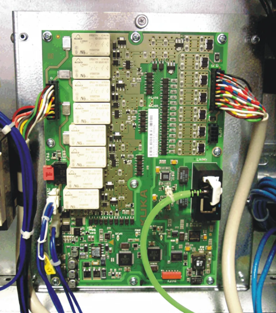
- X11 connector + SIB (Safety Interface Board): Safety signals are connected to the X11 connector via cables. The SIB is the interface board used to connect safety signals.
Notes:
- The Profisafe and CIP-Safety methods are commonly used in automotive plants. The X11 connector method is more common in general-purpose applications such as material handling, palletizing, and arc welding.
- KUKA safety signals use dual-channel wiring to ensure system safety.
Safety Signals — X11 Connector Wiring
Because Profisafe and CIP-Safety are configured via software protocols and implemented in the associated PLC programming, this section describes only the wiring for safety signals connected through the X11 connector.

The X11 wiring varies by control cabinet model.
KR C4 standard, KR C4 Mid-size and KR C4 Extend control cabinets
Emergency stop, safety gate, and safety light curtain signals should be connected to the corresponding safety devices. If a channel is not required, short the corresponding pins as shown below.
X11 connector assignments:
- Emergency stop: Channel A: 1-2?Channel B: 19-20
- Safety gate: Channel A: 3-4?Channel B: 21-22
- Safety confirmation: Channel A: 5-6?Channel B: 23-24
- Safe stop: Channel A: 7-8?Channel B: 25-26
For unused connector pairs, short as follows:
- Channel A: 9-10 shorted, Channel B: 27-28 shorted
- Channel A: 11-12 shorted, Channel B: 29-30 shorted
- Channel A: 13-14 shorted, Channel B: 31-32 shorted
Note: KUKA provides the safety interface; other equipment accessories must be supplied by the user.
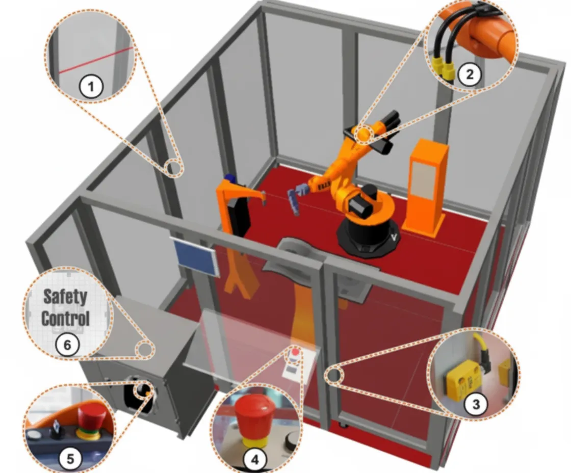
Component labels in the diagram:
- Protective fence
- Mechanical end stops or axis range limit devices for axes 1, 2 and 3
- Protective door and monitored door contacts with closing function
- External emergency stop button
- Emergency stop button, acknowledge button, key switch to call the connection manager
- Built-in KUKA (V)KR C4 safety controller