Overview
As finance, big data, and other industries expand, dependence on cryptographic devices increases and demands for higher levels of data security grow. New requirements include stronger physical protection of cryptographic modules, resistance to non-invasive attacks, and environmental-failure detection. Based on a security-level-2 cryptographic module, a higher-security cryptographic module is proposed by adding four key security technologies: physical security, entity authentication, environmental failure testing (EFT), and non-invasive attack mitigation. This design is intended for sectors with stringent data-security requirements.
1. High-Security Module Design Architecture
1.1 Hardware Architecture
The example design uses a high-speed serial expansion bus (PCI Express, PCI-E) cryptographic module. The module comprises a control unit, a PCI-E interface unit, cryptographic computation units, storage, an environmental failure testing (EFT) unit, and functional units.
In the high-security module: (1) the control unit is implemented by a central processing unit (CPU) running an embedded operating system and handles key management and parsing/responding to application-layer commands; (2) the PCI-E interface unit is implemented on an FPGA and serves as the primary data channel; (3) cryptographic computation is performed by two dedicated algorithm chips for SM1 and SM2, with logic devices implementing hash algorithm SM3 and symmetric block cipher SM4; (4) the storage unit uses double data rate synchronous dynamic random-access memory (DDR SDRAM) and flash (FLASH) to store runtime data and onboard executable code; (5) the EFT unit implements voltage and temperature sensing and response; (6) functional units include a cover-open destruction mechanism and manual zeroization button for emergency key erasure, LEDs to indicate module status, a USB key interface for identity tokens, and multiple physical noise sources for high-quality random number generation.
1.2 Software Architecture
The cryptographic module sits below the host application layer and is invoked by various security applications. The software stack consists of a security service interface, device drivers, and embedded software running on the module control unit.
The security service interface exposes cryptographic functions for direct application use; device drivers provide host-device support; embedded software executes and responds to application-layer calls.
1.3 Key Hierarchy
Keys are the module's core resource. The high-security module uses a three-layer key hierarchy to provide robust, practical key management.
In the layered key protection: the protection key at the top layer encrypts lower-layer user key pairs and key-encryption keys. The middle layer holds user key pairs and key-encryption keys; user key pairs are used for asymmetric operations and also protect session keys below. The bottom layer contains session keys, which are symmetric keys used only for a single session. Except for public keys, no keys exist in plaintext outside the module. This structure satisfies the "layered protection" principle in key management.
2. Physical Security Design
Key physical-security design points for the high-security module include the following.
(1) Use symmetric and elliptic-curve algorithm dedicated chips certified by the national cryptography authority. These chips offer high resistance to attacks and protect sensitive internal data such as keys and algorithm code.
(2) Place all critical components on the PCB top layer and enclose the PCB front and back in a fully wrapped rigid metal housing to prevent external inspection and probing. The metal housing can be aluminum alloy 6063, which offers good resistance to prying, drilling, and impact in common tamper attempts. The housing is compliant with the component specifications in national standard GB/T 3190-2020.
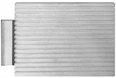
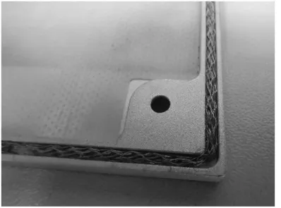
(3) The housing interior includes a metal wire mesh around the perimeter that tightly presses against the PCB when assembled, eliminating microgaps. This both reduces electromagnetic leakage and increases resistance to electromagnetic-analysis non-invasive attacks.
(4) Important bus signals and dedicated algorithm-chip data lines are routed on inner PCB layers to prevent direct probing if the surface coating is removed.
(5) The housing fasteners use a proprietary non-standard nut design requiring a vendor-specific tool; a metal cover plate hides the screws and a holographic tamper-evident seal marks any removal of the housing.
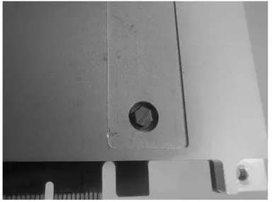
(6) A disassembly-detection circuit composed of mechanical detection units and a trigger-notification circuit is implemented. Mechanical detectors operate in parallel at three module corners; any detector sensing separation triggers the notification circuit, which alerts the CPU to zeroize unprotected critical parameters. The detection mechanism measures the vertical gap between the housing top and PCB at multiple points to reliably detect cover removal.
3. Entity Authentication
When using a USB token (UKey) for identity authentication, the module must confirm that the inserted token is the specific token associated with the module to prevent substitution attacks. The design adopts the two-pass one-way authentication mechanism from digital-signature specifications. The process is:
- During operator creation, the module uses the smart token cryptography application interface specification (SKF) to generate an asymmetric key pair on the UKey. The private key remains on the UKey and the public key is exported to the module.
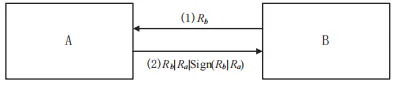
- For authentication, treat the UKey as the claimant A and the module as the verifier B.
- B generates a 32-byte random number Rb, sends Rb to A for later signing using A's private key.
- A receives Rb, generates a 32-byte random Ra, concatenates Ra and Rb, hashes the concatenation, signs the hash with A's private key, and sends Rb|Ra|sign(Rb|Ra) back to B.
- B hashes Rb|Ra and verifies the signature using A's public key, then checks that the returned Rb equals the original Rb.
- If verification and comparison succeed, entity authentication is successful.
4. Environmental Failure Testing (EFT)
The module implements EFT for temperature and voltage monitoring to detect four abnormal conditions: low temperature, high temperature, large negative voltage, and large positive voltage. The following sections describe the detection logic and response mechanisms.
4.1 Temperature Failure Detection
Multiple temperature sensors are placed near key devices such as programmable logic devices and algorithm chips to provide multi-point internal temperature monitoring. A working temperature range is defined. The CPU periodically reads temperature registers; if any sensor reports a temperature outside the allowed range, the CPU logs the event. If the condition persists across multiple consecutive readings, the CPU instructs the power switch circuit to cut module power, thereby zeroizing unprotected critical security parameters. The module power indicator LED will extinguish once power is cut.
4.2 Voltage Failure Detection
The PCI-E input power is split: one path goes through an analog-to-digital converter (A/D) into the CPU for monitoring; the other path supplies the module via the power switch circuit. The CPU periodically samples input voltage; if multiple consecutive samples fall outside the defined normal range, the CPU logs the event and commands the power switch to disconnect module power, causing the downstream circuits to lose power and zeroize unprotected critical parameters. The module power LED indicates on/off status: steady-on during normal operation and off after power cut.
5. Non-Invasive Attack Mitigation
5.1 Timing-Attack Mitigation
At the algorithm level, symmetric cipher SM4 has no key-dependent branching and is inherently immune to timing attacks, so no special timing protections are required for SM4.
For the SM2 public-key algorithm, a secure scalar multiplication algorithm is used to mitigate timing and simple power analysis (SPA) attacks. The algorithm processes one key bit per iteration, performing one point addition and one point doubling each time so that operations take constant time regardless of key bit values.
5.2 Power-Analysis Mitigation
For SM4, masking techniques randomize intermediate values so that power consumption is independent of data-dependent values, removing data-related correlations. The approach uses randomized masking of registers and masked S-boxes. For example, 16 distinct masked S-boxes can be generated and rotated across rounds so each encryption round uses a different set of masked S-boxes, ensuring every computational step includes masking and is independent of the unmasked algorithm state.
For SM2 signature operations, known differential and fault attacks target points where implementation details correlate with the private key, such as modular multiplication, or exploit weaknesses in the per-signature random number k. To mitigate these, the design uses secure scalar multiplication, transformed large-number modular multiplication formulas, and masking. Countermeasures include:
- Ensure the 256-bit random k is freshly and unpredictably generated for each operation, and add a backup operation that stores k to detect tampering.
- After k generation, verify that k is not equal to a forbidden value; if it is, abort the operation.
- Transform the large-number modular operations using algebraic rearrangements that remove easily attacked intermediate forms.
- Introduce a step counter incremented after each algorithm step; if the counter does not match the current expected step, abort processing to prevent skipping or replay attacks.
These measures, combined with secure scalar multiplication and masking, increase resistance to SPA, differential power analysis (DPA), and fault attacks that target k or exploit weak curves.
5.3 Electromagnetic Analysis Mitigation
For SM4, the electromagnetic (EM) defense strategy is to increase noise and reduce signal-to-noise ratio while applying masking to increase the number of EM traces required for an attack, making practical EM attacks computationally infeasible. For SM2, point-multiplication steps are implemented so that each iteration executes identical operations, removing data-dependent branching that would reveal key bits via EM traces. Addition masking is applied to modular multiplications and point operations involving the private key to randomize EM signatures and break the correlation between private key bits and observed EM curves, defeating DPA. The module also uses a fully enclosed metal housing with an inner wire mesh to minimize EM leakage; the sealed design prevents external probes from accessing chips or logic devices for direct EM measurement.
6. Conclusion
This article described the security requirements for a high-security cryptographic module and presented corresponding technical design measures. These targeted designs enhance module security and enable the module to meet varied user security needs. Compared with security-level-2 modules, a high-security module better protects data and communication security in daily use and can safeguard critical system data in the event of threats, offering a higher-assurance cryptographic service.
Reference: Zhou Jian, Qin Fang. Security-level cryptographic module security design. Communication Technology, 2022, 55(2):247-253.