Definition
A pressure monitoring system monitors and controls the pressure difference between stairwells, lobbies, and corridors to prevent smoke ingress and to maintain safe evacuation routes. A pressurization supply system introduces air at supply outlets to establish positive pressure in stairwells and firefighting lobbies. If supply volume or duration is uncontrolled, excessive positive pressure in the lobby can prevent fire doors from opening and cause serious consequences.
System Components
Main components: pressure monitor (display unit), pressure controller, damper actuator, and pressure detector.
Operating Mode
Pressure detectors measure the differential pressure between the lobby and corridor or between the stairwell entrance and corridor. When the measured pressure exceeds the preset threshold, the detector alarms and sends its status and data to the pressure controller. The pressure controller opens or closes the bypass damper via the damper actuator. Controller data are uploaded to the pressure monitor.
Interlock with Fire Door Monitoring
The pressure monitoring system and the fire door system operate independently and do not interlock.
Applicable Standard
Relevant standard: GB51251-2017 (China) "Technical Code for Building Smoke Control and Exhaust Systems". Key excerpts:
- Design of smoke control systems should consider building height and use, using natural ventilation or mechanical pressurization systems.
- For public and industrial buildings taller than 50 m, and residential buildings taller than 100 m, stairwell pressurization and associated lobbies and elevator lobbies should use mechanical pressurization.
- Mechanical pressurization should provide a pressure-increasing distribution from corridor to lobby to stairwell. Differential pressure requirements:
- Lobby or enclosed refuge room to corridor: 25 Pa to 30 Pa.
- Stairwell to corridor: 40 Pa to 50 Pa.
- If system pressure exceeds the maximum allowable differential, pressure relief measures must be taken.
- Mechanical pressurization systems should include pressure measurement and pressure regulation measures.
- Fire control equipment should display the operating status of smoke control fans, dampers, and related devices.
Recommended Installation Locations
- Pressure monitor (main unit): typically installed in the fire control room.
- Pressure controller: installed inside the pressurization fan control cabinet. Reserve one 220 V power supply in the control box for the controller.
- Damper actuator: installed on the bypass relief damper at the fan outlet duct.
- Pressure detectors:
- One detector per floor in stairwell lobbies or combined lobbies.
- Install detectors at approximately one-third and two-thirds of stairwell height, or at floors with pressurization outlets.
- Detectors should be located in the high-pressure area (near the evacuation door side in stairwell or lobby), wall-mounted at 0.2 to 0.5 m below the ceiling, and fixed to a standard 86 flush box.
- Detector sub-panels are installed in the same locations as detectors.
- One end of the tubing connects to the detector low-pressure port; the other end connects to the sub-panel.
Drawings Required for Quotation
HVAC drawings are required. The bill of materials for the project can generally be extracted from the HVAC drawings.
Wiring Requirements
- Communications between the pressure monitor and pressure controller: RS-485, daisy-chain (hand-in-hand) wiring, cable type NH-RVSP 2*1.5 mm2.
- Detector to controller: two-wire bus communication; power and signal share the same cable. Cable type NH-RVSP 2*2.5 mm2.
- Damper actuator to controller: multi-core flexible cable with seven color-coded cores (brown, yellow, black, red, blue, green, white), cable type RVV 7*0.75 mm2.
Pressure Setpoints for Stairwell, Lobby, and Corridor
According to GB51251-2017:
- Lobby or enclosed refuge room to corridor: 25 Pa to 30 Pa.
- Stairwell to corridor: 40 Pa to 50 Pa.
- If system residual pressure exceeds the maximum allowable differential, implement relief measures.
- Mechanical pressurization systems should include pressure measurement and regulation functions.
- Fire control equipment should display the status of fans and dampers.
Operation Without a Pressure Monitor
The pressure controller, detectors, and damper actuators can be deployed independently and perform local actions when an alarm occurs. However, omitting the pressure monitor makes it difficult to locate alarms and complicates maintenance. Installing a monitor is recommended for a complete pressure monitoring solution.
Monitor Communication Capacity
A pressure monitor provides two RS-485 communication loops. Each loop can connect up to 32 pressure controllers.
Monitor Installation Notes
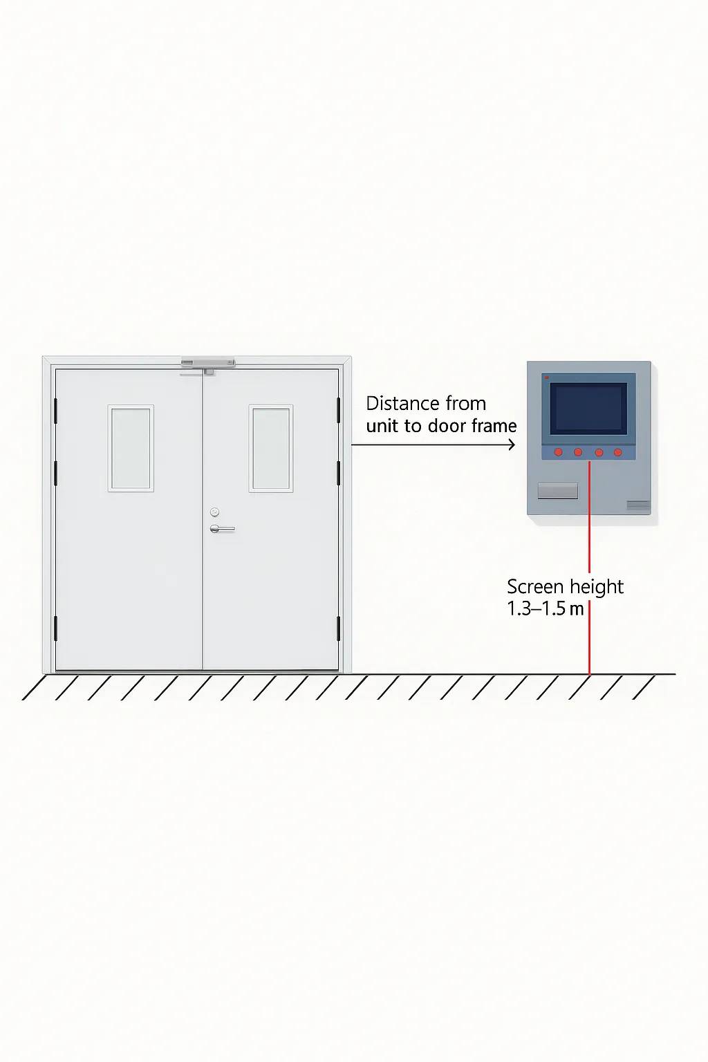
- Install the pressure monitor at least 1.5 m from the door. The monitor display should be 1.3 m to 1.5 m above the floor.
- Monitor enclosure dimensions: 400 mm (H) x 300 mm (W) x 160 mm (D).
- Required cutout size for installation: 320 mm (H) x 240 mm (W).
Communications and Distance Limits
- Monitor to controller communications: RS-485, maximum recommended distance 500 m.
- If the distance between the monitor and controllers exceeds 500 m, use a data acquisition box to extend communication range.
- Controller to detector communications: two-wire bus, maximum recommended distance 500 m.
Controller Operating Environment
Operating temperature range: -20°C to 60°C. If the environment is outside this range, apply insulation or ventilation measures. The controller must not be used in humid environments and should be installed inside a weather-protected distribution box.
Controller Features
- Each pressure controller can support up to 120 pressure detectors.
- Standard functions: one relay output, audible/visual alarm, LCD display, one RS-485 uplink, and one two-wire downlink.
Controller Power Supply
AC 220V ±15%, 50 Hz.
Third-Party Integration
The pressure controller is not compatible with third-party products.
Installation Without a Fan Box
If no fan box is available on site, provide a dedicated electrical enclosure to house the controller.
Pressure Detector Installation Notes
- Mounting height: 1.8 m to 2.2 m. Do not install the detector inside the ceiling void.
- Each detector has a factory-fixed unique ID code that must not be changed. Do not swap detector housings during installation to avoid commissioning issues.
- Record each detector's unique ID and corresponding floor for commissioning purposes.
Detector and Sub-Panel Purpose
The detector and its sub-panel measure the differential pressure between the lobby (or stair entrance) and the corridor.
Backbox and Tubing Requirements for Detectors
- Recommended backbox: standard 86 type flush box.
- Tubing conduit: DG galvanized conduit with set-screw joints (recommended), suitable diameters include 16 mm, 20 mm, 25 mm, 32 mm, 40 mm; or KBG national standard crimped conduit.
- Detector sub-panel mounting is the same as the detector.
Detector Power
Detector operating power: DC 24V, bus-powered.
Damper Actuator Function
The damper actuator receives commands from the pressure controller and controls the opening and closing of the bypass relief damper.
Can the Damper Actuator Control the Fan?
No. The damper actuator controls the bypass damper only and does not control the fan.