Access control systems are widely used in buildings, residential complexes, schools, and enterprises. This article summarizes common installation considerations and wiring practices for access control systems.
Overview
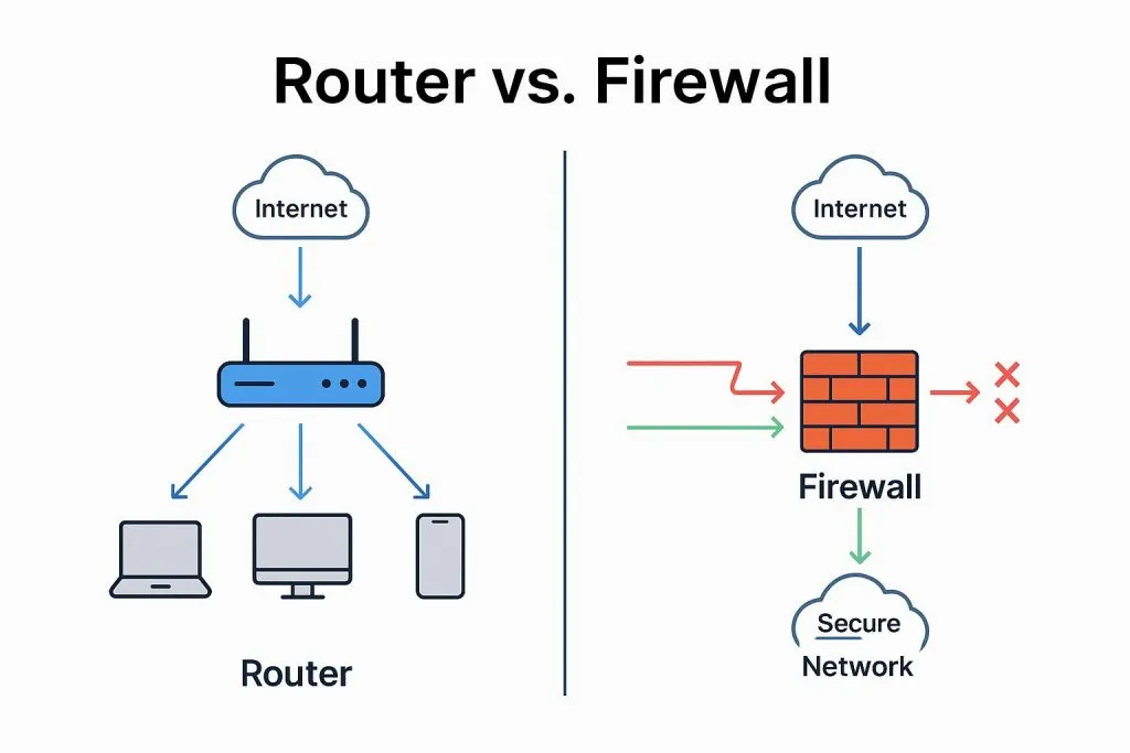
An access control system is a security management system that integrates computer-based automatic recognition technology with modern security measures.
1. Considerations Before Equipment Installation
Before installing an access control system, conduct a site survey to gather the following information.
First, determine whether the system will be networked or standalone. Networked systems are more complex. Establish the door structure and the type of lock to be used, the reader mounting locations, the location of the management center, and the distances between the management center, control units, and readers. Plan the cable routing, the power supply locations, and check whether raceways are in place.
Choose the lock type according to the door. Do not misplace or misalign lock cutouts. For example, glass doors, framed glass doors, and frameless glass doors require different lock mounting methods. Framed glass doors typically use electric strike locks mounted on the door frame, so the lock cutout is aligned with the frame. Frameless glass doors require glass door clamps and the lock cutout is offset toward the door interior. For wooden doors with insufficient thickness for an electric strike, use an electromagnetic lock and select an appropriate bracket location. Different finish materials at cutout locations may affect drilling; for example, marble should be drilled before installation to avoid complications.
Typical access control installation includes readers, controllers, locks, and buttons. The reader mounting location directly affects usability and installation difficulty, so plan locations carefully.
Site-specific guidance:
- For concrete or stone walls, use surface-mounted conduits or avoid marble sections when routing cables.
- For metal or stainless steel doors, avoid mounting readers directly on metal to prevent interference; remove metal at the mounting location if necessary. Use a plastic spacer under the reader to reduce interference.
- To support future expansion and ensure reliable communications, select controller locations carefully. If controllers communicate with the management computer over TCP/IP and cabling permits, consolidate controllers in an environmentally controlled equipment room or communications riser for easier maintenance. If distances are long, connect controllers to the network locally.
Reader-to-Controller Wiring
Use an 8-core shielded multi-strand twisted-pair cable, with three cores reserved. If the reader does not require audible/visual feedback, the LED lead can be omitted. Data lines Data1 and Data0 should be a twisted pair. Recommended conductor cross-section is 0.3 mm^2 or larger. Cable length should not exceed 100 m. Connect the shield to the controller GND.
For push buttons to controller, use two-core cable with conductor cross-section of 0.5 mm^2 or larger.
Lock-to-Controller Wiring
Use two-core power cable with conductor cross-section of 1.0 mm^2 or larger. For runs longer than 50 m, consider larger conductors or parallel conductors, or adjust the power supply output to about 14 V if the power supply supports fine adjustment. Maximum recommended run is 100 m.
For door contact (magnetic switch) to controller, use two-core cable with conductor cross-section of 0.3 mm^2 or larger. If the system does not require real-time door-open status or long-closed/unclosed and forced-entry alarm functions, the door contact line can be omitted.
Controller Installation Precautions
- Prevent electromagnetic interference: Install readers and push buttons away from strong electrical equipment. Where possible, locate readers at least 30 cm from high-power wiring or switches.
- Prevent signal attenuation: Consider the distance between controllers and readers; ideal transmission distance is within 100 m. Use shielded cable and account for signal loss over long runs. Use steel conduits and cable trays and ensure reliable grounding.
Wiring Best Practices During Installation
- All cabling should be routed in conduits. PVC or galvanized conduits are acceptable. Protect cables from rodent damage. Strongly recommend routing all system low-voltage cabling separately from 220 V mains in separate conduits.
- Although controllers have protections against electrostatic discharge, lightning, and leakage, ensure the controller chassis and AC earth are properly connected and that the AC earth is a true earth connection.
- Avoid hot-plugging wiring terminals while powered. Remove terminal blocks before soldering.
- Do not disassemble or replace controller integrated circuits unless performed by qualified personnel, as improper operation may damage the controller.
- Do not connect additional peripheral devices without consultation with a qualified engineer. Nonstandard operations must be evaluated before implementation.
- Electrical supply: Do not connect controllers and other high-current equipment to the same power outlet.
- Recommended mounting height for readers and buttons is 1.4 m above finished floor; adjust as needed for user habits.
- Install controllers in accessible locations for maintenance, such as inside the door frame on the secure side, ceiling voids, or communications risers.
- Wire terminations should be neat. Avoid long exposed conductor ends to prevent short circuits and communication faults.
- Where possible, solder wire-to-wire connections rather than relying on screw-wrap connections, which are more prone to poor contact.
2. Device Commissioning
- After installation, connect one reader channel to the host controller and independently test that reader for missed reads or false reads. Once that channel functions correctly, connect the next channel and repeat until all channels have been tested and then fully connect the system.
- Assign access permissions to users based on required time and location constraints. Verify that authorized and unauthorized openings are recorded by the management system.
- Test controller autonomy: if the management computer is unavailable, confirm that the controller can locally record events for its controlled doors and that records can upload automatically and completely once the computer reconnects.
- Keep detailed commissioning records.
- Complete the final acceptance report.
3. Conduit and Cable Installation
Cabling work should comply with applicable national electrical installation and acceptance codes and other relevant standards. Pulling cables into conduits or trays should occur after plastering and floor finish works. Remove water and debris from conduits or trays before pulling cables. Cables of different systems, voltage levels, or current types should not share the same conduit or the same slot within a tray. Conductors inside conduits or trays should not have splices or knots.
Wire splices should be made in junction boxes and secured by soldering or terminal connections. Small-section system conductors may be twisted with at least five turns, then tinned and wrapped with insulating tape. At building expansion joints, provide strain relief and allow adequate slack for movement. Terminal boxes should use crimp or tinned solder terminal blocks and be clearly labeled.
Controllers must be firmly mounted and level, with clear identification. When mounted on lightweight partition walls, reinforce the mounting. Incoming cables to controllers should be tidy and secured; conductors and cable cores should be labeled and match the drawings. Each terminal should have no more than two conductors. Provide at least 20 cm of spare conductor at cable ends. Bundle conductors with ties. Seal conduits at entry points after pulling cables.
Main power leads to controllers should be permanently connected to the supply and not use temporary power plugs. Mark the main power clearly. Ensure solid grounding of controllers with clear identification.
Grounding bus routing and specifications in the monitoring room should follow design requirements. During installation: grounding bus surfaces must be intact, free of damage and flux residues; copper busbars must be smooth and burr-free; insulation must be free of aging or cracking. Place grounding busbars centrally in trenches or cable routes and secure them to racks. Busbars should be flat without distortion. Securely fasten busbar connections to racks or cabinets. In cable trays, copper busbars may be fastened with screws; stranded copper busbars should be tied to cross members. Lightning protection and system grounding should be installed strictly according to design and coordinated with civil works.
4. Access Control Networking Methods
Access control systems are a security subsystem often integrated with video surveillance, parking control, and other security systems on a shared security network. Therefore, networked access control systems are now mainstream.
RS485 bus access control systems typically use daisy-chain connections. RVVP-type cable is commonly used.