In the trenches of SMT assembly lines, I've seen stencil choices make or break yields—turning a smooth 95% first-pass rate into a headache of bridging and insufficient paste. As component pitches shrink below 0.3mm for 5G modules and EV controls, selecting the right stencil material isn't optional; it's the linchpin for precision printing. Stainless steel SMT stencils dominate for their ruggedness, while nickel SMT stencils—especially electroformed variants—excel in finesse. But which wins for your run?
This face-off unpacks stencil material properties, from durability and cost to paste release efficiency, drawing on hands-on fixes from high-volume fabs and IPC-7525 guidelines (Note 1). We'll compare real metrics, troubleshoot common failures, and arm you with engineering decisions. If you're chasing optimal solder joints without ballooning budgets, read on—these insights stem from dissecting thousands of prints gone wrong.
Why SMT Stencil Materials Matter in Assembly
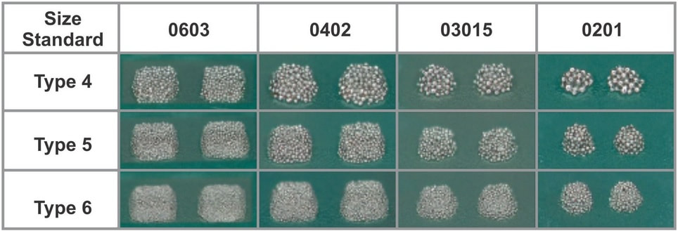
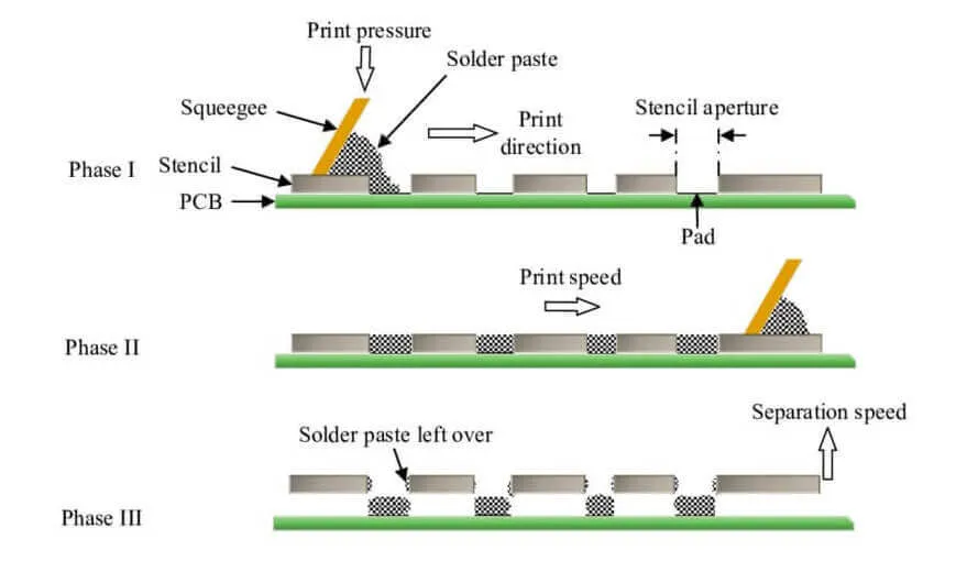
SMT stencil dictates solder paste deposition, directly impacting joint integrity and defect rates. Per IPC-A-610 Class 2/3 criteria, paste volume must hit 75-125% of spec for reliable reflow (Note 2). Material choice influences aperture walls, friction during squeegee sweeps, and longevity under 20-40mm/s print speeds.
Stainless steel SMT stencils, laser-cut from 300-series alloys, suit standard pitches (>0.4mm) and high-volume runs. Nickel SMT stencils, often electroformed, shine for ultra-fine features (<0.3mm) where smooth release trumps brute strength. In 2025, with HDI boards pushing area ratios below 0.5, mismatched materials spike defects by 15-20%—I've chased those ghosts in prototype ramps. Understanding stencil material properties ensures consistent transfer efficiency, cuts rework, and scales from low-mix to PCB mass production.
Stainless Steel SMT Stencils: Engineering Breakdown
Stainless steel, typically 0.1-0.15mm thick, forms the workhorse of SMT lines. Its austenitic structure (e.g., 304 or 316 grade) delivers tensile strength around 500-700 MPa, resisting deformation under 8-12kg squeegee pressure.
Key Stencil Material Properties
- Hardness and Surface Finish: Vickers hardness ~200 HV; as-cut Ra (roughness) 0.3-0.5μm. Electropolishing refines to 0.1-0.2μm, boosting release.
- Thermal Stability: Withstands 150-200°C reflow without warping, per J-STD-001 (Note 3).
- Chemical Resistance: Neutral to flux residues, minimizing swelling.
Durability in Action
These stencils endure >50,000 cycles in automated printers before aperture wear exceeds 10%. In my experience, unpolished edges erode faster in abrasive pastes, dropping yields after 30k prints. Common fix: Annual inspections via optical profilometry.
Paste Release Performance
Transfer efficiency hits 80-85% at area ratios >0.66, but dips to 60-70% for fine pitches due to sidewall adhesion. Trapezoidal walls from laser tapering help, aligning with IPC-7525's 1:1 aspect ratio max (Note 1).
| Property | Metric | Common Issue & Fix |
|---|---|---|
| Thickness Tolerance | ±5μm | Over-thick causes bridging; fix with post-cut calibration. |
| Aperture Taper | 5-10° | Insufficient release; electropolish for smoother walls. |
| Cycle Life | >50,000 | Edge burrs accelerate wear; use premium 316 alloy. |
Pros: Cost-effective at $50-150 per unit; scalable for 10k+ boards. Cons: Rougher than nickel, risking 5-10% more skips in <0.3mm apertures.
Nickel SMT Stencils: The Electroformed Edge
Electroformed nickel SMT stencils, grown layer-by-layer in a plating bath, yield ultra-smooth foils down to 0.08mm thick. The process etches photoresist on a mandrel, then deposits pure nickel (99.9%) to 100-150μm, dissolving the base for freestanding precision.
Key Stencil Material Properties
- Hardness and Surface Finish: ~250-300 HV; inherent Ra <0.1μm with vertical-to-trapezoidal walls (10-15° taper).
- Thermal Stability: Excellent up to 250°C, low CTE (13 ppm/°C) reduces distortion.
- Chemical Resistance: High, but swells 1-2% in aggressive fluxes—mitigate with post-plating rinse.
Durability Insights
Expect 20,000-30,000 cycles; nickel's hardness resists abrasion, but thinness invites dents from mishandling. In a 2024 fab audit, frameless nickel variants fatigued 20% sooner under high-speed sweeps—reinforce with mesh borders per IPC-7525 (Note 1).
Paste Release Performance
Stars here: 85-95% efficiency even at area ratios 0.5, thanks to low friction (0.2 vs. steel's 0.4). Trapezoidal geometry shears paste cleanly, cutting bridging by 12% in fine-pitch QFNs.
| Property | Metric | Common Issue & Fix |
|---|---|---|
| Thickness Uniformity | ±2μm | Plating inconsistencies cause skips; monitor bath chemistry. |
| Wall Smoothness | Ra <0.1μm | Flux swelling; bake at 120°C pre-use. |
| Cycle Life | 20k-30k | Dents from clamps; opt for framed designs. |
Pros: Ideal for <0.2mm apertures in HDI; superior for prototypes. Cons: $200-400 per unit; less forgiving in dirty environments.
Head-to-Head: Stainless Steel vs. Nickel SMT Stencils
No clear "supreme"—it hinges on pitch, volume, and budget. Here's the engineering scorecard:
| Category | Stainless Steel SMT Stencil | Nickel (Electroformed) SMT Stencil | Winner & Why |
|---|---|---|---|
| Stencil Durability | >50k cycles; robust for volume | 20-30k cycles; harder but thinner | Steel: High-run endurance (e.g., automotive). |
| Stencil Cost | $50-150; laser-cut efficiency | $200-400; electroforming overhead | Steel: 30-50% savings for >1k units. |
| Paste Release | 80-85% efficiency; good with polish | 85-95%; low-friction walls | Nickel: 10-15% better for fine pitch. |
| Fine-Pitch Suitability | Min 0.3mm; burr risk | Min 0.2mm; smooth release | Nickel: HDI/5G must-have. |
| Overall Yield Impact | Stable at >0.66 area ratio | Excels <0.5; reduces defects 10-20% | Tie: Match to app. |
From failure logs, steel fails via burr-induced bridging (fix: electropolish); nickel via swelling (fix: compatible pastes). Per 2025 trends, hybrid nano-coatings on steel close the release gap, per IPC-TM-650 tests (Note 4).
Best Practices for Stencil Selection and Maintenance
Engineer your choice upfront: For pitches >0.4mm and >5k runs, spec stainless steel with electropolishing (IPC-7525 Section 1.8.11 recommends (Note 1)). Fine-pitch? Electroformed nickel, verified via profilometer for Ra <0.1μm.
- Design Rules: Aspect ratio ≤1:1; area ratio >0.66 for 80%+ release. Add 5° tapers.
- Process Tweaks: Squeegee at 20-30mm/s; clean every 50 prints with IPA wipes.
- Troubleshooting Table:
| Failure Mode | Symptom | Root Cause | Engineering Fix |
|---|---|---|---|
| Insufficient Paste | Skips on pads | Poor release (Ra >0.2μm) | Polish steel or switch to nickel. |
| Bridging | Excess between pads | Over-volume from flat walls | Add trapezoids; reduce speed 10%. |
| Wear Acceleration | Aperture enlargement >5% | Abrasive paste | Upgrade to 316 steel or hard nickel. |
In my toolkit: Always prototype with both— a 10-board test run reveals 5-8% yield swings.
Case Study: Fine-Pitch Fiasco and Nickel Triumph
A med-device client hit 25% bridging on 0.25mm BGA pads with stainless steel stencils—root cause: 0.4μm Ra walls adhering paste. Switched to electroformed nickel: Release jumped to 92%, cycles held at 25k despite medium volume. Cost up 40%, but rework down 60%, netting 15% savings. Lesson: Pitch trumps budget; validate with IPC-7525 simulations.
Conclusion
Stainless steel SMT stencils reign for durable, cost-conscious volume; nickel SMT stencils supreme for precision paste release in fine-pitch realms. Weigh stencil material properties against your specs—durability for longevity, smoothness for yields. In assembly, the right pick slashes defects and scales reliably. Next time you're quoting, run the numbers: It'll pay off in every print.
FAQs
Q1: What are the key stencil material properties affecting stainless steel SMT stencil performance?
A1: Stainless steel offers 500-700 MPa tensile strength and Ra 0.3-0.5μm finish, enabling >50,000 cycles but risking burrs in fine apertures. Electropolishing refines to 0.1μm for better release, per IPC-7525 guidelines. Ideal for pitches >0.3mm; fix wear with premium 316 alloy (Note 1).
Q2: How does nickel SMT stencil durability compare to stainless steel?
A2: Nickel hits 250-300 HV hardness for 20-30k cycles with low friction (0.2 coefficient), but thinner foils dent easier. It's superior for abrasion resistance in medium runs, though stainless steel endures high-volume better. Common fix: Frame for support, aligning with J-STD-001 durability tests (Note 3).
Q3: What impacts stencil cost between stainless steel and nickel SMT stencils?
A3: Stainless steel runs $50-150 via laser-cutting efficiency; nickel's electroforming pushes $200-400 due to plating precision. For >1k units, steel saves 30-50%, but nickel justifies premium for fine-pitch yields. Factor lifecycle: Steel's longer life offsets initial outlay in volume.
Q4: Why is paste release better in electroformed stencil designs?
A4: Electroformed nickel's <0.1μm Ra and 10-15° trapezoidal walls achieve 85-95% efficiency at low area ratios (0.5), vs. steel's 80-85%. This minimizes adhesion, cutting bridging 10-20%. Per IPC-TM-650, test at 20mm/s speeds for verification (Note 4).
Q5: When should I choose stainless steel over nickel SMT stencil for assembly?
A5: Opt for stainless steel in high-volume (>5k boards) with pitches >0.4mm, where durability and cost win. It handles 8-12kg pressure reliably, but polish for release. Nickel for <0.3mm HDI; hybrid coatings bridge gaps in 2025 apps.
Q6: What common issues arise with stencil durability in SMT processes?
A6: Abrasion enlarges apertures >5%, causing skips; steel wears faster unpolished, nickel swells in fluxes. Fixes: Inspect every 10k cycles, use compatible pastes, and adhere to IPC-7525 for material specs. Yields improve 15% with proactive maintenance (Note 1).
(Note 1) IPC-7525C — Stencil Design Guidelines. IPC – Association Connecting Electronics Industries, 2023.
(Note 2) IPC-A-610H — Acceptability of Electronic Assemblies. IPC, 2019.
(Note 3) J-STD-001GS — Requirements for Soldered Electrical and Electronic Assemblies. IPC/JEDEC, 2020.
(Note 4) IPC-TM-650 — Test Methods Manual. IPC, 2023.