Introduction
In the intricate dance of surface mount technology (SMT) assembly, the stencil and solder paste are inseparable partners. The quality and characteristics of these two PCB Manufacturing Materials fundamentally determine the success of solder paste deposition, which in turn dictates the reliability and yield of the entire assembly process. As an assembly engineer, I consistently emphasize that understanding the nuances of stencil materials and solder paste material composition is not merely academic; it is critical for preventing defects, optimizing print quality, and achieving robust solder joints. This comprehensive guide will delve into the various types of stencils and solder pastes, their properties, and how they interact to form the cornerstone of a successful SMT line.
The SMT Stencil: A Precision Tool and Its Materials
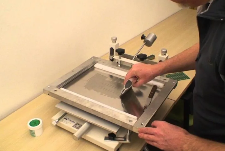
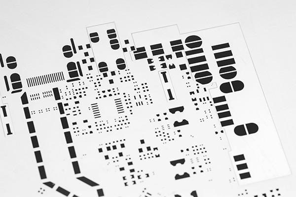
The SMT stencil is a thin, perforated sheet that controls the precise location and volume of solder paste applied to a printed circuit board. Its material is crucial for durability, aperture definition, and most importantly, clean solder paste release.
1. Stainless Steel Stencils
Composition: The most common stencil material, typically made from high-grade stainless steel alloys.
Manufacturing Method: Primarily produced by laser cutting. Earlier methods involved chemical etching, but laser cutting offers much finer feature resolution.
Advantages:
- Cost-Effective: Generally the most economical option.
- Durability: Good mechanical strength and resilience, making them suitable for high-volume production.
- Versatility: Can be used for a wide range of component pitches, from larger passive components down to moderately fine pitch (e.g., 0.5 mm pitch).
Disadvantages:
- Aperture Wall Quality: While laser cutting is precise, the aperture walls can sometimes have slight roughness or slag compared to electroformed stencils. This can slightly impede paste release for the finest pitch apertures.
- Limited Fine Feature Capability: For ultra fine pitch components (e.g., 0.3 mm or 0.25 mm pitch), achieving optimal paste release can be challenging due to aperture wall friction.
2. Nickel Stencils
Composition: Made from nickel alloys.
Manufacturing Method: Primarily laser cut, similar to stainless steel.
Advantages:
- Improved Paste Release: Nickel generally has a smoother surface finish and better anti-stick properties than stainless steel, leading to improved paste release, especially for fine pitch applications.
- Better Fatigue Resistance: Offers enhanced durability and resistance to wear over long production runs.
Disadvantages:
- Higher Cost: Typically more expensive than stainless steel stencils.
3. Electroformed Stencils
Composition: Pure nickel, built layer by layer using an additive electrochemical process.
Manufacturing Method: Electroforming, where nickel is deposited onto a conductive mandrel with the inverse pattern of the apertures.
Advantages:
- Superior Aperture Wall Smoothness: Results in extremely smooth, vertical, and often trapezoidal aperture walls. This provides the best possible solder paste material release.
- Ultra Fine Pitch Capability: Ideal for ultra fine pitch components (0.3 mm pitch and below), micro-BGAs, and dense assemblies where minimal paste volume and excellent print definition are critical.
- Enhanced Durability: The process can create a harder, more robust nickel layer.
Disadvantages:
- Highest Cost: Significantly more expensive due to the specialized manufacturing process.
- Fragility: Can sometimes be more fragile than stainless steel if not handled carefully, particularly with very thin foil sections.
Related Reading: The Comprehensive Guide to SMT Stencil Engineering: From Design Optimization to Process Control
Solder Paste: The Conductive Medium
Solder paste is a thixotropic mixture of finely powdered solder alloy and a flux system. Its properties are crucial for successful printing and reliable reflow. IPC J-STD-004B (Requirements for Soldering Fluxes) and J-STD-005A (Requirements for Solder Pastes) provide standards for these materials.
1. Solder Alloy Composition
Lead-Free Alloys: The predominant choice due to RoHS directives. Common compositions include:
- SAC305 (Sn96.5/Ag3.0/Cu0.5): A widely used lead-free alloy offering a good balance of mechanical properties and reflow characteristics. Melting point ~217-220°C.
- SAC387 (Sn95.5/Ag3.8/Cu0.7): Similar to SAC305 but with slightly higher silver and copper content for improved reliability.
- Low-Temperature Solder Pastes (e.g., SnBiAg, SnBi): Used for temperature-sensitive components or substrates (e.g., flexible PCBs). Melting points can be significantly lower (e.g., 138-190°C).
- Eutectic vs. Non-Eutectic: Eutectic alloys melt and solidify at a single temperature. Non-eutectic alloys have a melting range, which can impact reflow profiles.
Impact on Stencil: The type of alloy (especially its melting point) defines the reflow profile, which in turn influences the acceptable thermal budget for the entire assembly, including how quickly paste can dry on the stencil if the print environment is not controlled.
2. Solder Powder Particle Size
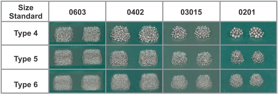
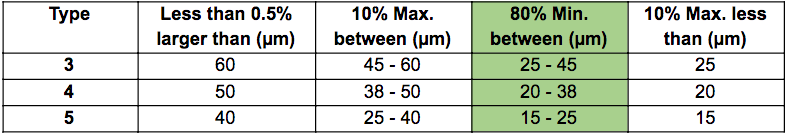
Solder powder is classified by type number, which corresponds to its particle size distribution.
- Type 3 (T3): (25-45 µm) – Standard for most SMT applications, suitable for 0.5 mm pitch components and above.
- Type 4 (T4): (20-38 µm) – Common for finer pitches (0.4-0.5 mm) and improved print definition.
- Type 5 (T5): (15-25 µm) – For ultra fine pitch (0.3 mm and below) and challenging applications.
- Type 6 (T6) and Type 7 (T7): Even finer, for specialized and emerging ultra fine pitch applications.
Impact on Stencil: Finer powder types (T4, T5) are essential for filling and releasing cleanly from smaller apertures on thin stencils. Larger particles can clog small apertures or lead to inconsistent paste deposition.
3. Flux System
The flux is a critical component of solder paste, cleaning surfaces and promoting wetting.
- Flux Type: Classified by activity level (R, RMA, RA) and halide content. No-clean fluxes are most common, eliminating the need for post-reflow cleaning.
- Rheology: This describes the paste's flow characteristics. Solder paste is thixotropic, meaning its viscosity decreases under shear stress (during squeegee stroke) and recovers quickly at rest (after printing).
Impact on Stencil: The flux system's rheology significantly influences how well the paste rolls on the stencil, fills apertures, and releases cleanly. A paste with optimized thixotropy will prevent slumping (paste spreading after printing) and maintain print definition. The flux residue can also contribute to stencil clogging if not properly managed.
Related Reading: Solder Paste: Working With Fine Pitch Components and Their Application
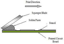
The Squeegee: Impact on Solder Paste Deposition
The squeegee blade is the unsung hero of solder paste printing, directly influencing how solder paste material interacts with the stencil.
1. Squeegee Material
- Metal (Stainless Steel): Preferred for fine pitch printing due to its rigidity and sharp edge. It creates a clean wipe and ensures consistent paste release.
- Polyurethane/Rubber: More common for older processes or larger pitch applications. More flexible, but can wear down faster and is less precise for fine features.
2. Squeegee Parameters
- Pressure: Critical for forcing paste into apertures and wiping the stencil clean. Too little pressure leads to insufficient fill and poor wipe; too much can damage the stencil or scoop paste from apertures.
- Speed: Influences how much the paste rolls and fills apertures. Optimized speed ensures proper paste rolling and complete aperture fill without smearing.
- Angle: Typically 45-60 degrees. Affects the force applied and the paste rolling action.
The squeegee impact is about creating the ideal hydrodynamic rolling of the paste across the stencil, ensuring every aperture is fully and uniformly filled before a clean separation occurs.
Optimizing the Stencil and Solder Paste Relationship
Achieving the optimum stencil and solder paste combination involves a holistic approach.
- Smallest Feature Dictates Stencil: The smallest aperture pitch on the PCB will often determine the minimum required stencil thickness and aperture wall quality. For ultra fine pitch, electroformed stencils with Type 4 or 5 solder paste are often the optimum stencil choice.
- Aperture Design for All Components: Even with the best stencil material, aperture design (reduction, windowpaning) is crucial to control paste volume for all component sizes for stencil.
- Solder Paste Rheology: Select solder paste with rheological properties tailored to the stencil material and printing conditions. A paste that rolls well, fills quickly, and releases cleanly is paramount.
- Environmental Control: Maintain consistent temperature and humidity in the printing area. This prevents solder paste from drying out on the stencil (clogging) or absorbing moisture (slumping).
- Regular Cleaning: Thorough and regular cleaning of the stencil (both automated underwipe and manual cleaning) is essential for consistent paste release, especially for fine pitch apertures. IPC-7525C (Stencil Design Guidelines) provides updated guidance on stencil cleaning.
Conclusion
The synergy between stencil materials and solder paste material is a cornerstone of modern SMT PCB Manufacturing Materials. From the precision and release characteristics of electroformed nickel stencils to the fine particle size and optimized rheology of advanced solder pastes, every material choice significantly impacts the integrity of the final product. Understanding the squeegee impact and meticulously selecting the optimum stencil for the specific application are vital steps for assembly engineers. By mastering these material considerations and their interactions, manufacturers can minimize defects, enhance print quality, and ultimately produce highly reliable electronic assemblies, driving efficiency and reliability in the fast-paced world of electronics production.
FAQs
Q1: What are the main types of stencil materials and their key differences?
A1: The main types of stencil materials are stainless steel, nickel, and electroformed nickel. Stainless steel is cost-effective and common. Nickel offers improved paste release and durability. Electroformed stencils provide the smoothest aperture walls and best paste release, ideal for ultra fine pitch, but are the most expensive.
Q2: How does solder paste particle size affect stencil printing?
A2: Solder paste material particle size critically affects stencil printing, particularly for fine pitch components. Finer particle sizes (e.g., Type 4 or Type 5) are necessary to fill and release cleanly from small stencil apertures. Larger particles can clog apertures or lead to inconsistent paste deposits.
Q3: What is the role of the squeegee in solder paste application?
A3: The squeegee impact is to apply even pressure across the stencil, forcing solder paste material into the apertures and wiping the stencil surface clean. Optimized squeegee pressure, speed, and angle ensure proper paste rolling, complete aperture fill, and clean separation from the stencil, preventing defects.
Q4: How do I choose the optimum stencil for a PCB with ultra fine pitch components?
A4: To choose the optimum stencil for ultra fine pitch components (e.g., 0.3 mm pitch), an electroformed nickel stencil is generally preferred due to its superior aperture wall smoothness and precise features. It should be paired with a fine particle size solder paste material (Type 5 or finer) to ensure excellent paste release and print definition.
References
IPC J-STD-004B — Requirements for Soldering Fluxes. IPC & JEDEC, 2200.
IPC J-STD-005A — Requirements for Solder Pastes. IPC & JEDEC, 2012.
IPC-7525A — Stencil Design Guidelines. IPC, 2007.
IPC-7525C — Stencil Design Guidelines. IPC, 2022.