Introduction
Electromagnetic compatibility (EMC) is critical for reliable drone operation. Unmanned aerial vehicles integrate multiple high-speed digital systems, power electronics, RF transmitters, and sensitive sensors in a compact, vibration-heavy environment. Poor EMI control can cause image loss, GPS failures, reduced flight range, and certification failures under CE, FCC, and other standards. For PCB manufacturers serving the aerospace sector, near-field EMI testing and mitigation during design and prototyping are essential to ensure system stability and regulatory compliance.
Drone Platform Architecture Overview
Modern drones feature integrated subsystems including:
- Flight controllers (e.g., DJI, ZeroTech, MWC, APM architectures)
- Electronic Speed Controllers (ESCs)
- Brushless motors
- Camera/gimbal assemblies
- Power distribution systems
- RF video transmitters and communication modules
These subsystems create complex electromagnetic interactions that must be carefully managed through robust PCB design and targeted testing.
Major EMI Sources in Drones
Common sources of electromagnetic interference include:
- Camera and Gimbal Assemblies: Clock signals, DSP processors, and high-speed video interfaces generate harmonics.
- Flight Controller Clocks: Microcontrollers (e.g., STM32 series) and IMUs (e.g., MPU-6000) produce fundamental frequencies and multiples.
- Motors and ESCs: Brushless motors and switching circuits create significant broadband noise.
- Power Subsystems: DC-DC converters and battery distribution lines radiate emissions through wiring and ground loops.
These issues can lead to radiated and conducted EMI, degrading wireless links (2.4 GHz / 5.8 GHz) and sensor performance.
EMC Considerations: Radiated vs Conducted EMI
Conducted EMI propagates through wiring and power lines, typically at lower frequencies. Radiated EMI travels as electromagnetic waves at higher frequencies and is often generated by PCB traces, IC pins, and connectors acting as unintended antennas.
Since drones are battery-powered, conducted coupling between propulsion and control systems is a key concern. Near-field testing during R&D is particularly valuable as it provides localized, spatial data for precise source identification and mitigation - unlike far-field chamber testing used for final certification.
Near-Field EMI Testing Methods
Near-field testing uses a spectrum analyzer paired with magnetic (H-field) and electric (E-field) probes to scan components, traces, and connectors directly on the PCB or subsystem.
Key Benefits:
- Identifies specific radiating sources (e.g., clock lines, motor drivers, camera interfaces)
- Enables iterative debugging before full system integration
- Supports quantitative measurement of mitigation effectiveness
Typical test targets include flight control boards, ESCs, brushless motors, and camera modules.
Practical Case Studies and Mitigation Strategies
Camera Head EMI: CCD and CMOS camera systems often emit strong harmonics from MCLK, PCLK, and DSP clocks.
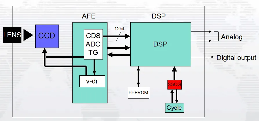
Mitigation: Implement spread-spectrum clocking on DSP crystals or main clock sources. This spreads energy across a wider frequency band, significantly reducing peak emissions while maintaining signal integrity.
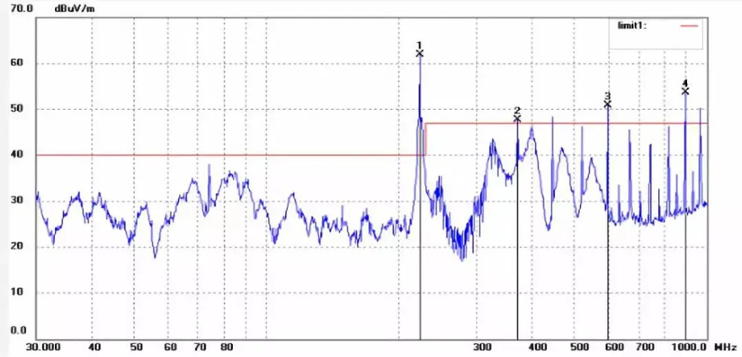
Flight Controller Clock Harmonics: Processors and IMUs generate discrete harmonic spikes.
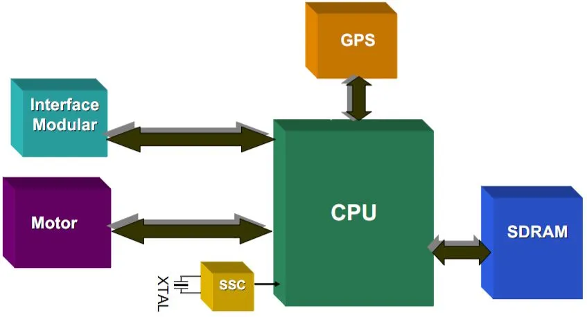
Mitigation: Apply spread-spectrum techniques to the main clock source, resulting in lower overall radiated emissions and improved system stability.
Motor-Induced EMI: Brushless motors and ESCs produce substantial switching noise.
Mitigation: Install Balanced Dual-Line (BDL) EMI filters close to motor connections. BDL filters offer superior common-mode rejection through paired reference electrodes and Faraday shielding, outperforming traditional filters in high-current aerospace applications. Additional high-frequency common-mode chokes help suppress ground imbalance issues.
PCB Design and Electronics Manufacturing Implications
Effective EMI control starts at the PCB level:
Layout Practices
Separate high-speed digital, power, and RF sections with proper grounding and partitioning. Use multilayer boards with dedicated power and ground planes. Implement short, shielded traces for clocks and high-speed signals. Apply guard rings and stitching vias for sensitive analog/sensor areas.
Material and Stack-up Choices
High-Tg laminates, controlled impedance, and low-loss dielectrics support RF performance and thermal stability under vibration.
Flexible and Rigid-Flex Solutions
Common in drone camera and motor connections to reduce mechanical stress while maintaining signal integrity.
Power Integrity and Filtering
Strategic placement of decoupling capacitors, ferrite beads, and EMI filters near noise sources minimizes conducted emissions.
Manufacturing Considerations
Precision assembly, conformal coating for environmental protection, and rigorous functional EMI pre-scans ensure high-yield, reliable production for aerospace-grade drones.
Industry Trends and Importance
As drones advance toward BVLOS operations, swarming, and higher autonomy, stricter EMC requirements are emerging. Proactive near-field testing and expert PCB design are key differentiators for manufacturers aiming for global market access and mission-critical reliability.
Supporting Drone EMC Through Advanced PCB Manufacturing
High-reliability PCB fabrication and assembly play a foundational role in drone electromagnetic compatibility. Expertise in multilayer design, RF optimization, power integrity, and integration of EMI mitigation components enables OEMs to build robust platforms that pass certification and perform reliably in real-world aerospace environments.
FAQs
Q1: What is near-field EMI testing and why is it important for drones?
A1: Near-field testing uses probes and spectrum analyzers to locate specific EMI sources on PCBs and subsystems during development, enabling targeted fixes before costly far-field certification testing.
Q2: What are the main EMI sources in drone systems?
A2: Primary sources include camera/gimbal clocks, flight controller processors and IMUs, brushless motors/ESCs, and power distribution circuits.
Q3: How can spread-spectrum techniques help with drone EMI?
A3: They reduce peak harmonic emissions by spreading clock energy across a wider frequency range, lowering radiated emissions while preserving signal quality.