Overview
Differential output is a circuit design technique used to extract changes in a signal and to amplify and process that signal. The input is amplified by a differential amplifier and then output as two signals with opposite phases.
Principle
The approach offers high common-mode rejection and strong noise immunity, reducing the effect of interference on the output. The basic principle of differential output is to extract useful information by comparing the difference between two input signals.
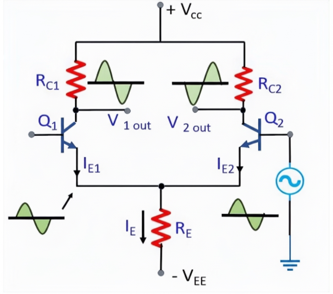
Differential input signals are amplified by a differential amplifier to produce a differential output. This design suppresses common-mode noise while amplifying the signal difference, improving the effective signal.
Advantages of Differential Output
There are several advantages to using differential outputs in circuit design. First, they can improve signal accuracy by removing shared error sources. In a differential input, the signal is the difference between two input terminals, which cancels several error sources such as power supply variations and mismatched line impedance. Second, differential outputs are highly immune to external electromagnetic interference (EMI).
An interfering source will typically affect both lines of a differential pair similarly. Because the signal value is determined by the voltage difference, any identical interference appearing on both conductors is largely ignored. In addition to reduced sensitivity to interference, differential signaling typically generates less EMI than single-ended signaling. Differential outputs also handle bipolar signals accurately; in a single-supply system, bipolar signals can be managed by properly establishing a virtual ground.
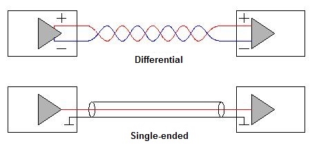
All circuits require a complete current return path to operate correctly. For single-ended circuits, the signal is carried by a single conductor relative to ground, so noise on the ground plane can affect all connected circuits. Differential signals use two conductors or PCB traces. The second conductor provides the return path, and the signals on the two conductors are complementary, with a 180 degree phase difference relative to the true signal. Unlike single-ended transmission, the return path for differential signals is dedicated to the pair.
Working Components
1. Differential generator: The differential generator produces the differential output signal. It is typically driven by a crystal or oscillator circuit that feeds a differential amplifier. The amplifier generates two signals that are equal in magnitude but opposite in polarity.
2. Differential transmission line: Differential transmission lines carry the differential output from the generator to the receiver. They are usually a pair of parallel conductors, one carrying the in-phase signal and the other carrying the inverted signal. Because the two signals remain balanced during transmission, interference and transmission loss are reduced.
3. Differential receiver: The differential receiver receives and decodes the differential output, converting it to a single-ended signal for subsequent circuits. The receiver has two inputs and one output; after differential amplification and decoding, a single-ended signal is recovered.
Summary
Differential output provides strong resistance to transmission line noise and interference. The difference between the in-phase and inverted signals can be used to eliminate common-mode noise and suppress interfering signals, improving noise immunity and signal integrity.